LEDs and Buttons
ARX®4000 Hardware Installation Guide
4 - 9
Data Plane LEDs
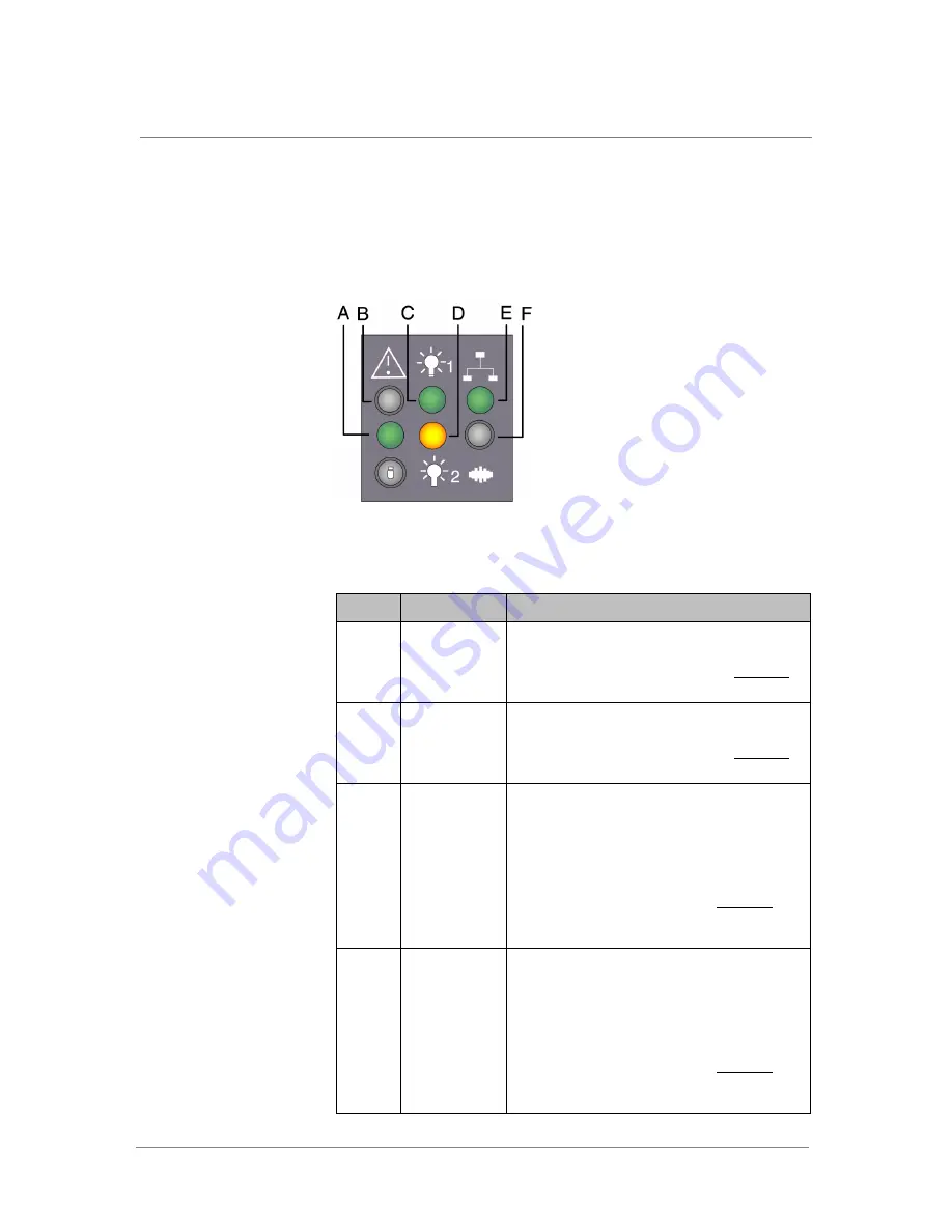
The following figure shows the LEDs available on the data plane. The LED
panel is on the front of the data plane in the lower left corner. The functions
associated with each LED are detailed in
.
Figure 4.6
Data Plane LEDs
Table 4.2
Data Plane LED Functions
Callout
Feature
Function
A
Status LED
For details on the LED colors and blinking patterns
that occur during various operational states, such
as booting, diagnostics, and so on, see
B
Alarm LED
For details on the LED colors and blinking patterns
that occur during various operational states, such
as booting, diagnostics, and so on, see
C
Power Supply 1
LED
Green. Power on.
Red. Fault indicated. When a fault is indicated, go
to the back of the data plane to the corresponding
power supply (PS 1, which is the power supply on
the right). Examine the 3 LEDS on the power supply
unit to gather additional information.
To assist in troubleshooting, consult
page 4-9 for a description of the power supply
LEDS and states,
D
Power Supply 2
LED
Green. Power on.
Red. Fault indicated. When a fault is indicated, go
to the back of the data plane to the corresponding
power supply (PS 2, which is the power supply on
the left). Examine the 3 LEDS on the power supply
unit to gather additional information.
To assist in troubleshooting, consult
page 4-9 for a description of the power supply
LEDS and states,
Summary of Contents for ARX-4000
Page 1: ...ARX 4000 Hardware Installation Guide version 4 00 001 810 0055 00 ...
Page 2: ......
Page 5: ...Table of Contents ...
Page 6: ......
Page 9: ......
Page 10: ...Table of Contents x ...
Page 12: ......
Page 22: ......
Page 28: ...Chapter 2 Product Overview 2 8 ...
Page 30: ......
Page 38: ......
Page 50: ......
Page 56: ...Chapter 5 Unpacking and Installing the Switch 5 8 ...
Page 58: ......
Page 70: ...Chapter 6 Connecting the Switch to the Network 6 14 ...
Page 72: ......
Page 76: ...Chapter 7 Operational Status and Troubleshooting 7 6 ...
Page 78: ......
Page 90: ...Appendix A Removing and Replacing FRUs A 14 ...
Page 91: ...Index ...
Page 92: ......


