4
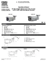
Figure :Connect the Wires
Step 6
Snap the wire connector into place.
After securing the wires, snap the wire connector into the base of the mounting bracket.
UP
Mounting Bracket
Wire Connector
Step 7
Place security light camera on the bracket
.
Step 8
Restore power at the breaker.
Align the mounting posts with the holes on security light camera
and press together, securing the base screw caps.
Turn on power to your security light’s circuit.
Base Screw Cap
Wires from your wall
Connect to Matching Wire on Camera
Yellow-green-Ground
Yellow-green
Brown-Hot
Brown
Blue-Neutral
Blue
Summary of Contents for LC1C
Page 2: ......
Page 10: ...6 SD PIR 180 360 360 SD EZVIZ 5 PIR PIR...
Page 12: ...8 3 1 2 2 3 4 UP 3 1 2 2 3 4 UP 5 1 2 3...
Page 13: ...9 6 UP 7 8...
Page 20: ...16 Micro SD PIR 180 360 360 Micro SD EZVIZ 5 PIR PIR...
Page 22: ...18 3 1 2 2 3 4 UP 1 2 3 4 UP 5 1 2 3...
Page 23: ...19 6 UP 7 8...
Page 30: ...26 Micro SD PIR 180 360 360 Micro SD EZVIZ 5 PIR PIR...
Page 32: ...28 3 1 2 2 3 4 UP 1 2 3 4 UP 5 1 2 3...
Page 33: ...29 6 UP 7 8...
Page 35: ...31 microSD PIR 180 360 360 microSD EZVIZ 5 PIR PIR...
Page 37: ...33 3 1 2 2 3 4 UP 3 1 2 2 3 4 UP 5 1 2 3...
Page 38: ...34 6 UP 7 8...
Page 47: ...UD16981B A...