


Page E-3
Service Parts Manual
ELECTRICAL
609694
Failure to follow these instructions can result in SERIOUS INJUR
Y or DEATH
THIS PROCEDURE SHOULD ONL
Y BE TO CLEAR VEHICLE FROM
AN UNSAFE
AREA AND BE PERFORMED
ONLY BY QUALIFIED
TRAINED PERSONNEL
In Case Of
Total Power Loss
And The ‘Run-tow’
Switch DOES NOT
Release The Brake
To Move The V
ehicle:
Turn the ignition key to the ‘OFF’
position and ‘chock’
tires to prevent inadvertent movement.
Connect ‘Auxiliary Power
’ line (3) to ‘Primary Power
’ line (1) which will release the brake.
THIS WILL
CAUSE THE VEHICLE
TO MOVE IMMEDIA
TELY IF NOT
ON LEVEL
GROUND.
Move vehicle to desired location and park it properly on level ground, chock tires, IMMEDIA
TELY
DISCONNECT
‘AUXILIAR
Y POWER’
AND RECONNECT
‘PRIMARY
POWER’ (1, 2) FOR SAFETY
AND TO A
VOID BATTER
Y DRAIN.
Reconnect the W
eather Pack Seal (4) to the
Auxiliary Power line (3) and perform required service
procedures following all Safety guidelines as outlined in your repair manual.
Identify the ‘Auxiliary Power
’ line (3) and remove the W
eather Pack Seal (4) from the connector
.
Identify the ‘Primary Power
’ line (1) connector and disconnect the line (2).
DO NOT alter or tamper with this unit. Unauthorized modifications can result in
SERIOUS INJURY or damage to the vehicle and will void the warranty
.
WAIT 30 seconds after reconnecting batteries BEFORE turning key switch to
‘REVERSE’, ‘FORW
ARD’ or ‘NEUTRAL’ positions.
TOWING - Always select ‘T
OW’
position before towing
STORAGE
612594
To disable electrical system, turn key switch to ‘OFF’
and remove battery wires.
ALWAYS turn key to ‘OFF’
before disconnecting or reconnecting
battery wires. ELECTRICAL
ARC or BATTERY EXPLOSION can
occur if key is not in the ‘OFF’
position.
Failure to follow these instructions can result in SERIOUS INJUR
Y or DEA
TH
Turn the ignition key to the ‘N’
position and ‘chock’ tires to prevent inadvertent movement.
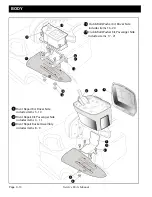
Remove this plastic cover by removing 3 plastic fasteners. See illustrations below
.
See emergency brake release instruction under this panel.
609987
Flip the RUN-TOW switch to the ‘T
OW’ position and move vehicle to the desired location and
park it properly on level ground and chock tires immediately
.
Turn the ignition key to the ‘OFF’
position, remove key and perform required service
procedures following all Safety Guidelines as outlined in your repair manual.
IF VEHICLE IS INOPERABLE
AND NEEDS T
O BE MOVED:
In Case of T
otal Power Loss and the ‘Run-tow’
Switch DOES NOT Release
the Brake to Move the V
ehicle :
Push center
of fastener
with vehicle
key ,
depressed
remove.
lift fastener to
When center is
T o
reuse fastener
push center stem
up then install
fastener
shield into
hole.
through
T o
secure fastener
in place press
down on
center stem
with head of
fastener.
until flush
12
13
14
16
3
6
5
9
17
1
Solenoid Electrical Harness (not shown)
(includes items 2, 7, 16 - 20)
7
11
Run Tow Switch Kit
(includes items 12 - 14)
Run Plug
not shown
15
2
Controller Splash Shield Assembly
(includes items 3 - 6)
8
Reverse Warning Indicator Kit
(includes items 9 & 10)
Main Electrical Harness (not shown)
(includes items 8, 11, 15)
10
not shown
4
ONLY POST PRODUCTION 23rd JAN 2012
20
18
21
22
23
Summary of Contents for RXV Electric 611105
Page 1: ...RXV ELECTRIC SERVICE PARTS MANUAL ISSUED FEBRUARY 2009 REVISED NOVEMBER 2015 611105 ...
Page 2: ......
Page 8: ...Page vi TABLE OF CONTENTS SECTION Page No Service Parts Manual FRAME R 1 Frames Seat Frames ...
Page 11: ...Page ix Service Parts Manual ILLUSTRATED PARTS BREAKDOWN ILLUSTRATED PARTS BREAKDOWN ...
Page 14: ...Page B 1 Service Parts Manual BATTERY CHARGER 1 2 ...
Page 20: ...Page C 5 Service Parts Manual BODY 6 3 1 2 21 20 21 20 12 13 19 14 15 15 16 17 5 7 7 ...
Page 32: ...Page C 17 Service Parts Manual Notes BODY ...
Page 33: ...Page C 18 Service Parts Manual Notes BODY ...
Page 36: ...Page D 3 Service Parts Manual BRAKES 6 5 4 3 1 ...
Page 52: ...Page E 15 Service Parts Manual ELECTRICAL 2 1 3 ...
Page 54: ...Page E 15 Service Parts Manual Notes ELECTRICAL ...
Page 55: ...Page E 16 Service Parts Manual Notes ELECTRICAL ...
Page 65: ...Page G 6 Service Parts Manual Notes FRONT SUSPENSION ...
Page 66: ...Page H 1 Service Parts Manual MOTOR 2 4 3 1 ...
Page 71: ...Page J 4 Service Parts Manual Notes REAR AXLE ...
Page 87: ...Page L 12 Service Parts Manual Notes REAR FACING SEAT EXCEED MODEL ...
Page 91: ...Page M 4 Service Parts Manual Notes TOW BAR ...
Page 97: ...Page M 10 Service Parts Manual Notes TOW BAR ...
Page 102: ...Page N 5 Service Parts Manual WEATHER PROTECTION 1 2 ...
Page 108: ...Page P 3 Service Parts Manual WHEELS AND TIRES 2 3 1 4 ...
Page 112: ...Page R 3 Service Parts Manual Notes FRAME ...
Page 113: ......


