Page | 10
It is assumed at this stage that you have already poured a reinforced concrete pad for anchoring your
VPL.
5.1.
Assemble the VPL a few inches away from its final position, and carefully reposition as required.
VPLs are top heavy; use extreme caution when moving VPLs.
5.2.
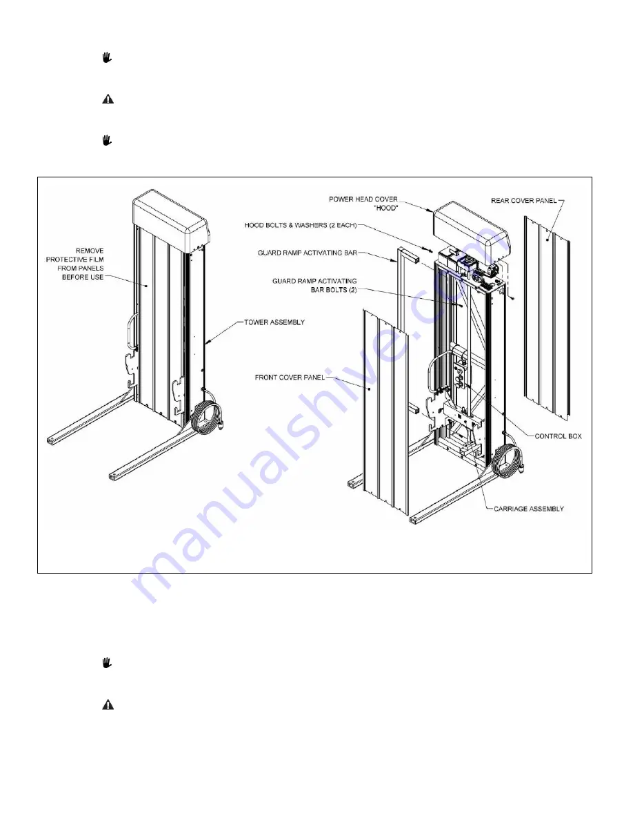
Remove the power head cover
(“hood”)
first by removing the two button head bolts on either end (FIG. 5.1).
5.3.
If attached, remove the front and rear tower covers and set aside.
For lifts taller than 72”, refer to the PASSPORT® Vertical Platform Lift (VPL) Installation
Supplement
for 120” (10’), 144” (12’), and 168” (14’).
FIG. 5.1
5.4.
Locate the guard ramp activating bar (FIG. 5.1).
5.5.
Determine which side of the platform will have the guard ramp (the guard ramp activating bar must always
be installed on the same side as the guard ramp).
5.6.
Attach the guard ramp activating bar in the two open holes on the corresponding side of the tower using
two 5/16”
-
18 x 1” long attachment
bolts.
There are two holes in the tower used for mounting the guard ramp activating bar which do not have
fasteners in them. This is normal since the guard ramp activating bar can be mounted on either side.
5.7.
Tighten all fasteners securely.
The turn platform guard ramp activating bar extends further away from the tower than the straight
platform guard ramp activating bar. This extension for the straight platform is approximately 7-
7/8”
and approximately 12-
3/8” for the
turn platform. The correct guard ramp activating bar must be used
with its intended platform for the guard ramp to operate correctly and to prevent damage.


