background image

Establishing Communication via eyeDevice Setup

This section describes how to establish the communication with the devices 

with the help of the eyeDevice Setup software.


)

NOTE

The illustrations and certain descriptions in this manual may vary due to 
development process.

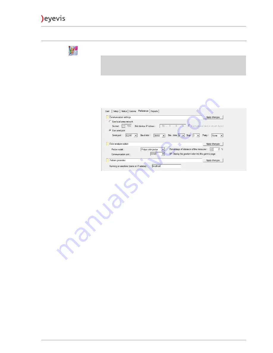
Establishing communication


Open the 

Preference

 page.


ª

The serial connection via RS232 interface 

(Use serial port)

 is selected as 

standard.

To use the serial port:

1.  In the 

Serial Port

 entry field, select the COM port to which the protector is 

connected.

2. 

For the remaining settings, the standard values should match the ones 

displayed in the screenshot.

3. 

Press 

Apply changes

 to apply the new settings.


ª

You can check if the connection is active on the Reports page.

To establish a connection via Ethernet (optional):


A connection is established to the first device via the Ethernet cable.

1.  Select 

Use local area network

.

2. 

Enter the IP address to the connected device (the first device).

3. 

For the remaining settings, the standard values should match the ones 

displayed in the screenshot.

4. 

Press 

Apply changes

 to apply the new settings.


ª

You can check if the connection is active on the 

Reports

 page.

5. 

eyeDeviceSetup.exe

EYE-LCD-4600/5500-M-USN-LD-BC

49

Version 1.0 | Oktober 2014

Summary of Contents for EYE-LCD-4600-M-USN-LD-BC

Page 1: ...eyeLCD 4600 5500 M USN LD BC EYEVIS LCD LINE User Manual Version 1 0 Oktober 2014 Technical changes reserved...

Page 2: ...licated according to the terms of the licence No part of this documentation may be reproduced stored in databases or transferred in any form electronically mechanically on recording media or in any ot...

Page 3: ...31 Input source connections 31 Controlling the Display 32 The Remote Control 32 Opening the On Screen Display OSD 32 Navigating in the OSD Menu 32 Selecting a display 32 Special keys and key sequence...

Page 4: ...dvised procedure for raising a claim 64 Consider the manual before raising a claim 64 Prepare necessary information 64 Approval by eyevis 64 Service code RMA number 64 Packing 64 Transport 64 Costs no...

Page 5: ...Revision History Version Date Page Section Description 1 0 2014 10 All Specification first issued EYE LCD 4600 5500 M USN LD BC 3 Version 1 0 Oktober 2014...

Page 6: ...r death In the text section the general warning symbol is used in conjunction with the warning levels described below CAUTION Indicates a hazard that could lead to minor or moderate injuries WARNING I...

Page 7: ...a place where water may splash onto it Be careful of equipment which drains water such as an air conditioner Ventilation The vents and other openings in the cabinet are designed for ventilation Do not...

Page 8: ...commended by the manufacturer Heat sources Keep the product away from heat sources such as radiators heaters stoves and other heat generating products including amplifiers Batteries Incorrect use of b...

Page 9: ...per clips or pins enter the monitor as this could lead to fire or electric shock Do not place the monitor on top of unstable objects or in unsafe places Do not allow the monitor to receive strong shoc...

Page 10: ...nitor Do not use the power cord with a power tap Adding an extension cord may lead to fire as a result of overheating Do not remove or insert the power plug with wet hands Doing so could result in ele...

Page 11: ...the monitor is not overhanging the edge of the supporting furniture Not placing the monitor on tall furniture for example cupboards or bookcases without anchoring both the furniture and the monitor to...

Page 12: ...rd das allgemeine Warnsymbol in Verbindung mit den nachfolgend beschriebenen Warnstufen verwendet VORSICHT Kennzeichnet eine Gefahr die zu leichten oder mittleren Verletzungen f hren kann WARNUNG Kenn...

Page 13: ...e bzw Zubeh rteile besteht evtl Unfallgefahr Wasser und Feuchtigkeit Benutzen Sie das Ger t nicht in der N he von Wasser Montieren Sie das Ger t unter keinen Umst nden an einer Stelle an der Wasser da...

Page 14: ...dass der Service Techniker nur die vom Hersteller bezeichneten Teile oder Teile mit gleichen Eigenschaften und gleichem Leistungsverm gen wie die Originalteile verwendet Die Verwendung anderer Teile k...

Page 15: ...Standbild ber l ngere Zeit hinweg anzeigen da dies ein Nachleuchten am Bildschirm zur Folge haben k nnte Vermeiden Sie es den Monitor mit harten Gegenst nden abzureiben oder zu ber hren Wir bitten um...

Page 16: ...t und leicht zug nglich ist Das Netzkabel dient als eine Trennvorrichtung Das Netzkabel Besch digen Sie das Netzkabel nicht stellen Sie keine schweren Gegenst nde darauf und berdehnen oder knicken Sie...

Page 17: ...en Monitor niemals auf ein gro es M belst ck z B einen Schrank oder in ein B cherregal ohne sowohl das M belst ck als auch den Monitor an einem geeigneten Element sicher zu verankern Stellen Sie den M...

Page 18: ...s ou la mort Dans le texte le symbole d avertissement g n ral est utilis en conjonction avec les niveaux d alerte d crits ci dessous PR CAUTION Indique un danger qui pourrait provoquer des blessures m...

Page 19: ...Eau et humidit N utilisez pas cet appareil pr s de l eau N installez pas le produit un endroit o il pourrait recevoir de l eau vitez en particulier les emplacements sous les appareils vidange d eau t...

Page 20: ...aroi installez le en respectant la m thode recommand e par le fabricant Sources de chaleur Tenez l appareil l cart de sources de chaleur telles que radiateurs dispositifs de chauffage po les et autres...

Page 21: ...e poussi res o le degr d humidit est lev ou encore l o il pourrait se trouver en contact avec de l huile ou de la vapeur car cela pourrait provoquer un d but d incendie Assurez vous que le moniteur ne...

Page 22: ...trique Utilisez seulement le cordon d alimentation fourni avec le moniteur Ne branchez pas le cordon d alimentation sur une prise multiple Ajouter une rallonge peut entra ner une surchauffe et provoqu...

Page 23: ...r que le moniteur ne d passe pas du bord du meuble sur lequel il est pos Ne pas placer le moniteur sur des meubles hauts armoires ou tag res par exemple sans fixer le meuble concern et le moniteur un...

Page 24: ...play extremely fine pictures with this eyevis display 3200 Kelvin version for TV studios Thanks to a special treatment of the panel surface this version is especially designed for video wall installat...

Page 25: ...or Way of packaging The eyevis display is packed in a carton box To provide protection during transportation the EYE LCD display is surrounded with foam The packaging is secure with banding and fasten...

Page 26: ...d simple mounting in a video wall system Optional wall mounting kit Optionally eyevis provides wall mounting kits for the displays from the EYE LCD M series These wall mounting kits consist of wall mo...

Page 27: ...einstallation of the video wall The individual stacking frames are fixed together with screws or optionally with snap closings Special ventilation duct Optional display rack eyevis also provides displ...

Page 28: ...mbly of video walls is the optional stacking frame for the EYE LCD M series displays These stacking frames allow for a simple and fast assembly of your video wall and provide special ventilation ducts...

Page 29: ...stacking frames row by row 2 Fix the stacking frames together 3 Hang in the displays row by row 4 Align the displays before operation 2 4 3 1 Landscape Portrait installation The EYE LCD M series can b...

Page 30: ...olution cable lengths cable quality graphic cards etc For video wall sizes comprising more than 9 displays the signal has to be split up see Example video wall matrix 4x4 No Daisy Chain for video sign...

Page 31: ...ations Video wall with 46 displays Individual unit 46 ca 579 mm Housing 1 080 Pixel ca 1025 mm Housing 1 920 Pixel ca 46 Screen ca 1158 mm 2 160 Pixel ca 2050 mm 3 840 Pixel ca 92 Screen Diagonal Conf...

Page 32: ...ys Individual unit 55 ca 687 mm Housing 1 080 Pixel ca 1216 mm Housing 1 920 Pixel ca 55 Screen ca 1374 mm 2 160 Pixel ca 2432 mm 3 840 Pixel ca 110 Screen Diagonal Configuration 2x2 Configuration 5x5...

Page 33: ...6 S Video Mini DIN 4 pol 7 C Video 1 BNC 8 C Video 2 BNC 9 DIP Switches Force Address 1 Not used Not used Not used Enable debug and error messages Enable verbose debug and error messages only use this...

Page 34: ...on the number block If using the arrow buttons for entering numerical values holding the keys pressed will toggle larger steps Selecting a display A display can be addressed in the main menu Alternati...

Page 35: ...ection of the arrow and snap it back into place Used batteries needed to follow the city rule to be discarded Avoid keeping used old batteries inside the remote control causing leakage of internal liq...

Page 36: ...size transformation Press or ENTER to enter the sub menu Matrix Adjustments of splitting output over several displays Press or ENTER to enter the sub menu Analogue RGB Settings Adjustments of the anal...

Page 37: ...put Source DVI 1 Autoscan On Input Input Source Selects the input of the display Press or to select the desired input source and then press ENTER Options DVI 1 DVI 2 RGB 1 RGB 2 CompV1 CompV2 S Video...

Page 38: ...the backlight Press or to select the desired option and then press ENTER Options On Off Backlight Adjusts the backlight of the display Press or to select the desired level and then press ENTER Range 0...

Page 39: ...l resolution of the image H Size Information about the linear stretching in horizontal direction V Size Information about the linear stretching in vertical direction H Offset Adjustments of advanced s...

Page 40: ...Range 1 10 Element X Adjusts the horizontal matrix position of the selected display Press or to select the desired position and then press ENTER Range 1 10 Element Y Adjusts the vertical matrix posit...

Page 41: ...urces Press or to select the desired position and then press ENTER Range depends on input source Options Enables using only the internal timing table Press or to select the desired option and then pre...

Page 42: ...osed before Set Netboard Value can be executed Network Configuration Netboard IP Address Adjusts the IP address of the display Press or to select the desired value and then press ENTER Netboard Netmas...

Page 43: ...nput board reset Framelock Video Activates or deactivates the Framelock for video input Press or to select the desired position and then press ENTER Option On Off Framelock RGB Activates or deactivate...

Page 44: ...to return to the main menu Status Ok only read Fan 3 Speed The current speed of Fan 3 only read Press or MENU to return to the main menu Range 0 255 only read Fan 3 Status Shows whether Fan 3 is dete...

Page 45: ...70I02VI Info LCD Panel String description of the LCD panel only read Press or MENU to return to the main menu CPU HW Version Hardware version of the CPU Press or MENU to return to the main menu CPU FW...

Page 46: ...can enter five different configurations that can be combined or used separately Every configuration consists of an interval of days of the week and both a Power On and a Power Off time Entries are onl...

Page 47: ...lation and start The programs do not have to be installed 1 Simply copy the entire program folder to the desired location you wish on your PC example C Software 2 Open the exe file to launch the progr...

Page 48: ...onnel The password required is available from the eyevis service Enter the password and confirm with OK b User This is the normal user type no service settings are possible Confirm with OK without ent...

Page 49: ...of the active device The factory device settings can thus be restored at any time Read current Reads the current settings of the active device The settings are then displayed in the parameter area Sav...

Page 50: ...atus information of the device Gamma Settings of the individual colours red green blue Preference Settings of the communication to the device Reports All software status messages are collected in this...

Page 51: ...For the remaining settings the standard values should match the ones displayed in the screenshot 3 Press Apply changes to apply the new settings You can check if the connection is active on the Repor...

Page 52: ...Click and hold the left mouse button in a field and mark the relevant area 2 Click on Read current The data of the selected devices are displayed in the view window Saving the configuration Once you...

Page 53: ...ing for input signals on off Matrix Enable Matrix Switch the Matrix Function on or off To enable the matrix Set Matrix must be executed afterwards to apply the configuration Size X Size Y Set horizont...

Page 54: ...by the ambient light sensor This value can only be set if an ambient sensor is attached to the display Set Backlight Dark Use the current ambient sensor and LCD panel backlight values as reference va...

Page 55: ...to be performed at program startup do nothing read default values read current values read a file Field by Field scanning Do not use accelerated protocol click check box to disable Max number of field...

Page 56: ...Temperature of the DVBPM Board Fan Sensor 1 Temperature Temperature of Fan Sensor 1 Fan Sensor 2 Temperature Temperature of Fan Sensor 1 Ambient Sensor Value of Ambient Sensor 0 if not installed Power...

Page 57: ...rd is data 8 stop 1 Parity Standard is None Apply changes Accepts the new settings You can check on the Reports page if the connection is active Color analyzer option Probe model Selects a predefined...

Page 58: ...eated file from the file directory The selected file is added to the Send window and can then be sent to the selected devices by clicking on Send NOTE Only administrators have the authorisation to sen...

Page 59: ...may cause a fire or an electric shock Immediately remove the power plug from the outlet Make sure that the smoke or smell has stopped then contact your dealer for inspection CAUTION Liquids or objects...

Page 60: ...nisms Heavy Image Sticking may be reversed by long switch off of the LCD TFT displays Image Sticking of TFT panels is excluded from the warranty Mura Further effect is Mura a Japanese term for unevenn...

Page 61: ...rs per day enlarges the life time of the product decisively and reduces the risk of image retention NOTICE Operating time for static images The operating time should not be longer than 20 hours a day...

Page 62: ...ts on page 61 Pollutions By the production process and handling of the displays occurs kinds of pollution in range of vision It applies to inclusions blistering depressions marks scratches The followi...

Page 63: ...5 n 0 0 2xn 10 XGA 1024 x 768 0 786 million pixel 2 2 4 4 n 0 0 2xn 8 SXGA 1280 x 1024 1 310 million pixel 3 3 7 7 n 0 0 2xn 14 WXGA 1366 x 768 1 049 million pixel 3 3 6 6 n 0 0 2xn 12 WXGA 1440 x 900...

Page 64: ...his specialist supplier point of purchase immediately about the defect Otherwise the product will be treated under usual terms of warranty Return to Base Warranty Bring In Warranty Defective parts or...

Page 65: ...ear and tear or defects caused by lack of service and maintenance e g cleaning the filter Act of God fire flood aggressive chemical aggressive biological activity event of war vandalism accidents etc...

Page 66: ...Packing The customer has to pack the defective device properly in the original box to label it as fragile and to attach the RMA number visibly on the box eyevis can provide a new original box on reque...

Page 67: ...e The policy sum regarding all requirements of the warranty does not exceed at discretion of eyevis the original purchase price of the product or alternatively the costs of substitution of the product...

Page 68: ...4 mm 1216 687 106 5 mm 1216 687 234 5 mm Bezel Width 1 8 mm bottom right 3 7 mm top left mechanical Active to Active 5 7 mm Weight Display with Stacking Frame 36 kgs 52 kgs VESA Mount 400 400 400 600...

Page 69: ...Appendix Dimensions EYE LCD 4600 M USN LD Dimentions in mm EYE LCD 4600 5500 M USN LD BC 67 Version 1 0 Oktober 2014...

Page 70: ...5500 M USN LD Dimentions in mm 103 4 687 4 1216 6 400 00 460 00 400 00 600 00 1112 24 52 18 52 18 52 18 583 04 52 18 24 5 24 5 all fixing points are threaded M8 EYE LCD 4600 5500 M USN LD BC 68 User...

Page 71: ...Frame EYE LCD 4600 M USN LD Dimentions in mm Frame EYE LCD 5500 M USN LD Dimentions in mm EYE LCD 4600 5500 M USN LD BC 69 Version 1 0 Oktober 2014...

Page 72: ...are and database Updating firmware of the CPU To update the firmware of the CPU 1 Switch off the LCD device 2 Create a direct serial connection with a cable between the display and a COM port of your...

Page 73: ...MENU and press OK 5 Open the drop down menu and select the according hardware 6 Choose the firmware version you want to install 7 Switch the LCD on and the firmware update starts You can see the prog...

Page 74: ...update 4 Open the Service tab press the button ERASE THE DATABASE and restart the display 5 Now select the option Create the device Database in the service tab and the following windows appears 6 Sel...

Page 75: ...5 Start the Flash Upgrader Software 6 Choose Connection Serial 7 Choose Baud Rate 115000 8 Select the appropriate COM Port where the flasher cable is connected to 9 Press the Flash Button 10 Power on...

Page 76: ...eyevis displays carefully Acceptable characteristics Panel damages caused by handling mistake external shock and vibration Light leakage side view Visible sheet guide boss clip side view Panel damage...

Page 77: ...h mechanical design margin Left side Right side Bottom side Holding and moving Hold each side of the module with keeping the same height Hold the display on top of the chassis to avoid damaging your d...

Page 78: ...cm 15 cm 20 cm EYE LCD 4600 5500 M USN LD 1 passed failed 2 passed failed 3 passed passed failed 4 passed failed Panel 1 Panel 2 Panel 3 Panel 4 Twist Angle Phenomena Panel broken after assembly and...

Page 79: ...rotary switches Sending commands using ID 0 is a broadcast to all connected devices Use carefully to avoid unintended overwriting of existing values Flow control needs to be implemented by control sy...

Page 80: ...Response DATA 1 Input 0 Query the current input source for display 1 Current Input Source is Display Port SAVE ID ALL ID Display address Command SAVE 1 ALL Response ACK 1 All actual parameters will be...

Page 81: ...55 200 Set Backlight Ambient Values Bright Set Backlight Bright Only relevant if Ambient Sensor is used Set Backlight Ambient Values Dark Set Backlight Dark Video Color Video Color 0 255 128 Video Tin...

Page 82: ...ues depend on input source Advanced Scaling V Linearity V Linearity 0 9990 2500 Only if Scaling is set to User Applicable values depend on input source Analogue RGB Settings Source Auto Adjust Autoadj...

Page 83: ...and to set range SETBLOCK 1 Scheduler 2 Mon Fri 08 00 00 12 00 00 Use Set Command to activate SET 1 Scheduler 2 1 Power Scheduler Time and Day of week range entry 3 Scheduler 3 WWW WWW HH MM SS HH MM...

Page 84: ...ON SCREEN DISPLAY 32 NAVIGATING 32 OPENING 32 OSD MENU 34 POWER SCHEDULER 44 P PACKAGING 23 BOX CONTENT 23 PIXEL 60 POLLUTIONS 60 BLISTERING 60 DEPRESSION 60 INCLUSION 60 LINT 60 MARK 60 SCRATCH 60 PO...

Page 85: ...Notes...

Page 86: ...0 7121 4 33 03 0 Fax 49 0 7121 4 33 03 22 Hotline 49 0 7121 4 33 03 290 netPIX eyeCON Hotline 49 0 7121 4 33 03 291 Cubes Displays web www eyevis de e mail info eyevis de service service eyevis de Ve...

Reviews: