IR Speed Dome Installation Manual
Appendix 3 Wire Gauge Standards
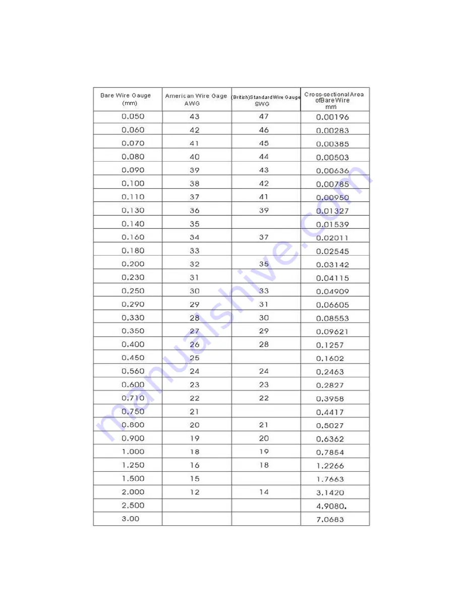
Table 4.3 Wire Gauge Standards
38
www.eyesoniccctv.com
Page 1: ...Installation Manual www eyesoniccctv com...
Page 2: ...ILITY AND FITNESS FOR A PARTICULAR PURPOSE REGARDING THE HIKVISION SOFTWARE HIKVISION DOES NOT WARRANT GUARANTEE OR MAKE ANY REPRESENTATIONS REGARDING THE USE OR THE RESULTS OF THE USE OF THE HIKVISIO...
Page 3: ...nicipal waste in the European Union For proper recycling return this product to your local supplier upon the purchase of equivalent new equipment or dispose of it at designated collection points For m...
Page 4: ...er rated voltage and current No user serviceable parts inside the power supply System Grounding Earthing To avoid shock ensure that all AC wiring is not exposed and that the earth grounding is maintai...
Page 5: ...and Mechanical Injury Some components such as heat sinks power regulators and processors may be hot care should be taken to avoid contact with these components Electro Magnetic Interference This equi...
Page 6: ...sure that the endure ability of ceilings or walls is 4 times as the weight of speed dome and its accessories 1 Preparation of cables Choose the video cable according to the transmission length The vi...
Page 7: ...20 Chapter 2 Mount Selection 21 2 1 Long Wall Mount 21 2 2 Short Wall Mount 22 2 3 Corner Mount 23 2 4 Pole Mount 23 Chapter 3 Mounting Instructions 24 3 1 Wall Mounting 24 3 1 1 Components 24 3 1 2...
Page 8: ...oden walls you need to mount the base with self tapping screws Please make sure that the wall is sturdy enough to withstand more than 3 times of the weight of the dome and the bracket If not the dome...
Page 9: ...the lock screws on the fast mounting adapter screw the top cover to the adapter and fasten the lock screws with the L shaped wrench Figure1 3 Install the Top Cover Figure1 4 Fasten the Lock Screws 4...
Page 10: ...ve Stickers 5 Install the sealing loop or waterproofing and tie the safety lanyard to the dome Network High definition IR Speed Dome network IR Speed Dome Figure1 6 Install the Sealing Loop Network Hi...
Page 11: ...ard For cabling please refer to section 1 2 to see more details Network High definition IR Speed Dome network IR Speed Dome Figure1 8 Hang the Dome to the Top Cover 7 Fasten the set screws to reinforc...
Page 12: ...dome L m 50 S while for network IR speed domes L m 40 S For example if the cross sectional area of bare cable is 1mm the transmission distance of IR speed dome and network IR speed dome should not ex...
Page 13: ...7 Find the alarm input output cables You can distinguish the cables by color and labels Eg Audio output cable in orange with label AUDIO_OUT please refer to Figure 1 10 and Figure 1 11 for more infor...
Page 14: ...IR Speed Dome Installation Manual Figure1 12 Bottom Circuit Board of IR Speed Dome Figure1 13 Bottom Circuit Board of Network IR Speed Dome 14 www eyesoniccctv com...
Page 15: ...250VAC Diagram left Diagram right 30mA OUT n OUT n DC DC Load Relay Output Dome OUT n OUT n Figure1 15 Alarm Connections To connect external alarm devices external power supply is required as below 1...
Page 16: ...code 0 baud rate 2400 120 matched resistor OFF Before you start Please remove the grounding screw from the circuit board if electromagnetic interferences exist Figure1 16 Bottom Board of IR speed dome...
Page 17: ...FF 9 ON OFF OFF ON OFF OFF OFF OFF 10 OFF ON OFF ON OFF OFF OFF OFF 11 ON ON OFF ON OFF OFF OFF OFF 12 OFF OFF ON ON OFF OFF OFF OFF 13 ON OFF ON ON OFF OFF OFF OFF 14 OFF ON ON ON OFF OFF OFF OFF 15...
Page 18: ...FF ON ON OFF OFF 51 ON ON OFF OFF ON ON OFF OFF 52 OFF OFF ON OFF ON ON OFF OFF 53 ON OFF ON OFF ON ON OFF OFF 54 OFF ON ON OFF ON ON OFF OFF 55 ON ON ON OFF ON ON OFF OFF 56 OFF OFF OFF ON ON ON OFF...
Page 19: ...of SW2 are used for protocol settings Please Refer to Table 1 4 for details DIP Switch SW2 Protocol Settings Protocol Type Positions 4 6 Settings 4 5 6 Bosch Manchester ON 1 2 3 4 5 6 7 8 SW2 OFF ON...
Page 20: ...unication Type Settings 1 3 5 Terminal Resistor Connection Settings Position 8 of SW2 is used for terminal matched resistor settings DIP Switch SW2 Terminal Resistor Connection Settings State Position...
Page 21: ...IR Speed Dome Installation Manual Chapter 2 Mount Selection 2 1 Long Wall Mount Figure2 1 Long Wall Mount Figure2 1 Long Wall Mount Dimensions 21 www eyesoniccctv com...
Page 22: ...IR Speed Dome Installation Manual Figure2 2 Wall Mount with Power Supply Box 2 2 Short Wall Mount Figure2 3 Short Wall Mount Figure2 4 Short Wall Mount Dimensions 22 www eyesoniccctv com...
Page 23: ...IR Speed Dome Installation Manual 2 3 Corner Mount Figure2 6 Corner Mount 2 4 Pole Mount Figure2 7 Pole Mount 23 www eyesoniccctv com...
Page 24: ...an 3 times the weight of the dome and the bracket If not the dome may fall and cause serious damage 3 1 Wall Mounting Notes 1 Wall mounting is applicable to indoor outdoor suspending domes For outdoor...
Page 25: ...lied into the mounting holes Figure3 3 Drill the Holes in the Cement Wall 2 Screw hex nuts padded with flat washers through the wall mount and the rubber gaskets with the expansion screws to secure th...
Page 26: ...e mounting holes 2 Secure the power supply box to the wall with nuts and washers Tighten the four expansion screws Figure3 5 Install the Power Supply Box 3 Position the wall mount to the power supply...
Page 27: ...rner constructions 3 2 1 Components 1 Mounts A corner mount has to be used together with a wall mount for corner mounting applications Figure3 7 Corner Mount Figure3 8 Corner Mount and Wall Mount 2 Mo...
Page 28: ...pening of the corner mount Note Make sure the cables are long enough For outdoor applications you can use sealant to seal the cable openings for waterproofing 3 Secure the mount to the corner by using...
Page 29: ...er to Chapter 1 for dome installation 3 3 Pole Mounting Applications Note Pole mounting is applicable to the indoor outdoor pole constructions 3 3 1 Mounting Components 1 Mounts A pole mount has to be...
Page 30: ...wall mount There are following dimensions selectable 59 82mm 84 108mm 103 127mm 130 152mm 155 178mm 180 203mm and 194 216mm Dimensions can be customized according to users demand Note The dimensions o...
Page 31: ...t them through the holes of the mount Figure3 16 Assemble the Hoops and the Pole Mount 2 Pass the power cord video cable and control line through the opening of the pole mount Note Make sure the cable...
Page 32: ...he wall mount fasten the hexagonal screws with the spring washers through the wall mount and the gaskets and tighten them with the pole mount Figure3 18 Install the Wall Mount 6 Install the dome to th...
Page 33: ...erstorm situations or high induction voltage areas such as areas of high voltage transformers high power lightning protection apparatus and lightning conductor are necessary 5 The installation wiring...
Page 34: ...IR Speed Dome Installation Manual Figure4 1 Lightning Protection and Grounding 34 www eyesoniccctv com...
Page 35: ...e 2400BPS 1800m 4800BPS 1200m 9600BPS 800m Table 4 1 Matched Resistance Settings The transmission distance may decrease if a thinner cable is used or the device is under a strong electromagnetic inter...
Page 36: ...tings 5 RS485 Distributer Installation In star shaped construction as shown in Figure4 4 terminal resistors are normally installed to the end devices with a long spacing distance eg In Figure 4 4 devi...
Page 37: ...IR Speed Dome Installation Manual Figure4 5 RS485 Distributer Figure 5 6 FAQ about RS485 Bus Table 4 2 RS485 Bus FAQs and Solutions 37 www eyesoniccctv com...
Page 38: ...IR Speed Dome Installation Manual Appendix 3 Wire Gauge Standards Table 4 3 Wire Gauge Standards 38 www eyesoniccctv com...
Page 39: ...INNOVATIVE CUSTOMIZED CCTV SOLUTIONS www eyesoniccctv com...