Extron electronics YCS SW6 MX User Manual Download Page 6

YCS SW6 MX • Installation and Operation

YCS SW6 MX • Installation and Operation

Installation and Operation, cont’d

2-3

Installation and Operation

Installation

Rear panel features

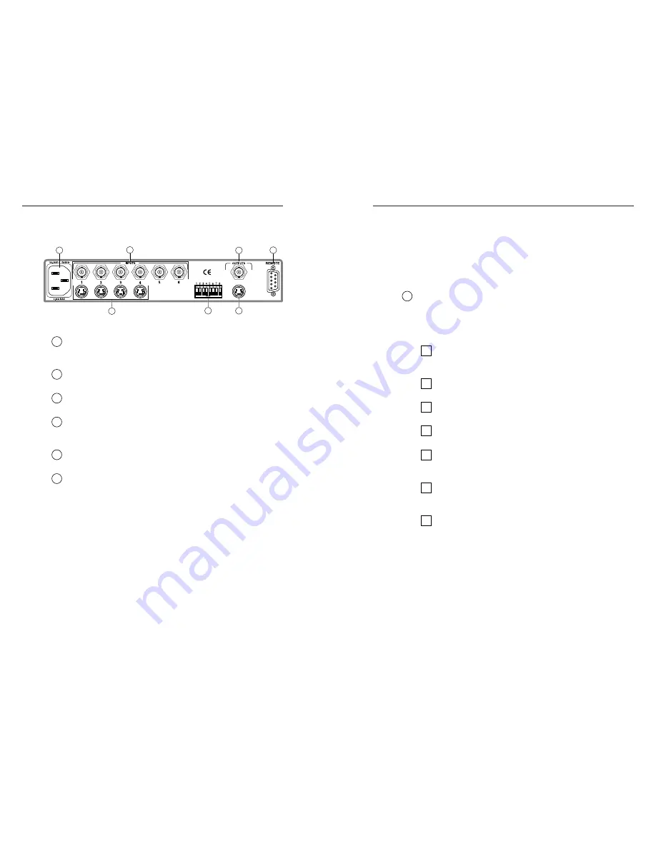
Figure 1 — YCS SW6 MX rear panel

1

AC power connector —

 One standard AC power connector

attaches the switcher to any power source from 100VAC to
240VAC, operating at 50 or 60 Hz.

2

Input BNC connectors —

 Six BNC female connectors for

composite video input devices.

3

Output BNC connector —

 One BNC female connector for a

composite video output device.

4

Remote connector —

 One 9-pin D female RS-232 connector that

allows you to attach a host/computer, contact closure, or
infrared remote control device to the switcher.

5

Output 4-pin mini-DIN connector —

 One 4-pin mini-DIN

female connector for an S-video output device.

6

Switch module —

 DIP switch module that selects between

composite video and S-video for inputs 1 – 4, and selects
between NTSC and PAL.

1 — Input 1

Up — Input 1 is composite video.
Down — Input 1 is S-video.

2 — Input 2

Up — Input 2 is composite video.
Down — Input 2 is S-video.

3 — Input 3

Up — Input 3 is composite video.
Down — Input 3 is S-video.

4 — Input 4

Up — Input 4 is composite video.
Down — Input 4 is S-video.

2-2

5 — Not used

6 — Not used

7 — Not used

8 — Video standard

Up — Video standard is NTSC.
Down — Video standard is PAL.

7

Input 4-pin mini-DIN connectors —

 Four 4-pin mini-DIN

female connectors for S-video input devices.

Installation procedure

To install a YCS SW6 MX switcher, perform the following steps:

1

If desired, mount the switcher in a rack (see “Mounting
the switcher”, below).  Otherwise, install the rubber feet
(see “Installing the rubber feet” on page 2-4).

2

Turn off power to the input and output devices ,and
unplug the power cables from them.

3

Attach the switcher to the input devices and output
devices (see “Cabling” on page 2-4).

4

Set the DIP switches on the switcher (see item 6 on
page 2-2).

5

If desired, attach an optional or third-party remote control
device (see “Attaching remote control devices” on page 2-
5).

6

Plug the switcher, input devices, and output devices into a
grounded AC source, and turn on the input and output
devices..

7

The image from the selected input device should appear
on the output device.  If it does not, double-check steps 3 –
5, and make adjustments as needed.

Mounting the switcher

The YCS SW6 MX switcher can be rack mounted on one side of
an optional 19”, 1U Universal Rack Shelf (Extron part number
60-190-01).  To rack mount the switcher, do the following:

1.

If feet were previously installed on the bottom of the
switcher, remove them.

2.

Mount the switcher on the rack shelf as shown in figure 2.
Attach two 4-40 x 1/8 screws in opposite (diagonal)
corners to secure the switcher to the shelf.

1

2

3

4

5

6

7

Summary of Contents for YCS SW6 MX

Page 1: ...3 4040 Fax 31 33 453 4050 Extron Electronics Asia 135 Joo Seng Road 04 01 PM Industrial Building Singapore 368363 65 6383 4400 Fax 65 6383 4664 Extron Electronics Japan Daisan DMJ Building 6F 3 9 1 Ku...

Page 2: ...artung Alle Wartungsma nahmen sollten nur von qualifiziertem Servicepersonal durchgef hrt werden Die internen Komponenten des Ger tes sind wartungsfrei Zur Vermeidung eines elektrischen Schocks versuc...

Page 3: ...ront panel features 2 7 Selecting an input 2 7 Chapter 3 Serial Communication 3 1 RS 232 Programmer s Guide 3 2 Switcher initiated messages 3 2 Switcher error responses 3 3 Using the command response...

Page 4: ...ii YCS SW6 MX Table of Contents Table of Contents cont d YCS SW6 MX 1 Chapter One Introduction Features...

Page 5: ...The switcher can be configured to operate in either NTSC or PAL mode Inputs Six inputs are provided Four can be used as either composite video or S video and two are dedicated to composite video Built...

Page 6: ...ard is NTSC Down Video standard is PAL 7 Input 4 pin mini DIN connectors Four 4 pin mini DIN female connectors for S video input devices Installation procedure To install a YCS SW6 MX switcher perform...

Page 7: ...the switcher 5 Turn the switcher right side up and place it in the desired location Cabling the switcher Use high resolution cable for all video input and output connections See page A 4 for Extron s...

Page 8: ...nused side of the adapter s RS 232 T connector 3 Plug the IR detector s male plug into the IR 20 adapter s RJ 11 female connector 4 Connect the 9VDC power supply to the IR 20 adapter 5 Position the IR...

Page 9: ...SW6 MX Installation and Operation Installation and Operation cont d YCS SW6 MX 2 8 3 Chapter 3 Serial Communication RS 232 Programmer s Guide Universal SW Control Program Remote Contact Closure Operat...

Page 10: ...nding a message to the host No response is required from the host The switcher initiated messages are listed below underlined C COPYRIGHT 1997 EXTRON ELECTRONICS YCS SW6 MX Vx xx The switcher displays...

Page 11: ...S SW6 MX switcher is compatible with Windows 3 1 3 11 95 98 and NT It provides remote control of input selection Installing the software The Universal SW Control Program is contained on a single 3 5 d...

Page 12: ...ration The RS 232 connector provides a way to control the switcher from a remote contact closure device This is made possible by using pins that are not normally used by the RS 232 interface The conta...

Page 13: ...Video Gain Unity Bandwidth 30 MHz 3dB Crosstalk 60dB 3 58 MHz Video input Number signal type 4 NTSC PAL S video 6 NTSC PAL composite video Connectors 6 BNC female 4 4 pin mini DIN female Impedance 75...

Page 14: ...12 SHR1 12 26 383 07 SHR1 25 26 383 04 SHR1 50 26 383 05 SHR1 75 26 383 06 SHR1 100 26 383 03 SHR1 150 26 383 08 SHR1 200 26 383 09 SHR1 250 26 383 10 SHR1 300 26 383 11 S video cable Description Part...

Page 15: ...YCS SW6 MX Reference Information Reference Information cont d A 6...

Reviews: