XPA U 1004 SB and XPA U 2002 SB • Installation
11
9.
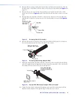
Install the conduit with the new conduit plate attached into the opening from where the
IEC connector removed in step 5 (see
figure 8
on page 10).
10.
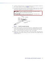
Connect the blue hot (line) and the brown neutral wires to the terminal block on the PCB
using the two screws removed back in step 3. Use the included zip tie wrap to secure
the two wires together close to the terminals (see figure 11).
WARNING:
Ensure that you observe correct wire polarity. The following illustration
shows the location of the hot (line) and neutral terminals.
AVERTISSEMENT :
Respecter la polarité correcte des câble. L’illustration suivante
indique l’emplacement des bornes de ligne et de neutre.
L N
Slide IEC
connector
plate and
conduit into
enclosue.
50-60
Hz
100-
240V
1.3A
Blue Wire
Brown Wire
Tie Wrap
Grounding Nut
Figure 11.
Install the Conduit Assembly
11.
Connect the ground wire, as shown in figure 13 above, to the grounding stud located
on the bottom of the enclosure using the nut removed in step
4.
Remove the ground
wire nut from the grounding stud located on the bottom of the enclosure as shown in
figure 11, above.
Place the nut with the other screws to be used later.
12.
Replace the cover of the XPA Ultra amplifier by reattaching the eight screws removed in
step
2.
Remove the 8 screws from the top, sides, and bottom of the amplifier then slide
and lift the cover off.
figure 11
Summary of Contents for XPA U 1004 SB
Page 7: ......


