background image

Extron • VTG 150 & VTG 200 • User’s Manual

Extron • VTG 150 & VTG 200 • User’s Manual

VTG 200 RS-232 Control and Software

Page 5-6

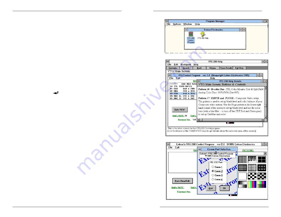
Figure 5-6A 

↑↑↑↑↑

Figure 5-6C 

↑↑↑↑↑

Figure 5-6B 

↑↑↑↑↑

VTG 200 RS-232 Control and Software

Page 5-5

VTG 200 Control Program

The 

VTG 200 Control Program is a Windows-compatible

program (requiring Windows 3.1 or later) that provides four
basic functions:

Remote control of the VTG 200 scan rate and test pattern

Listing VTG 200 scan rates and details of those rates

Adding new rates into the VTG 200 (one at a time)

Restoring, updating, or saving all scan rates for the VTG 200

Installing the Software

The program is contained on a single 3.5” diskette and will
run from the floppy drive. However, it is more convenient to
load and run it from the hard drive. It can be installed on the
user’s hard-drive as follows:

1. Insert the Extron software diskette into the floppy drive.

2. From the Windows File menu, click on Run.

3. Specify the disk drive and type “setup”. For example, type

A:SETUP 

 if the diskette is in drive A.

The program will occupy approximately 1 MB of hard drive
space.

The Windows installation will create (by default) a C:\VTG200
directory and will place 2 icons (

VTG 200 Control Program

and 

VTG 200 Help) into a group titled “Extron Electronics”.

See figure 5-6A.

Using the Software

1. For information about program features, double click on the

VTG 200 Help icon in the Extron Electronics group. Help
can be accessed from its icon (stand-alone) or from within
the program by the menu on the main screen or by pressing
F1 from within the control program. See figure 5-6B.

2. To run the software, double click on the VTG 200 Control

Program icon in the Extron Electronics group.

3. A Comm menu will be displayed on the screen. (See

Figure 5-6C.) Click on the Comm port that is connected to
the VTG 200 RS-232 connector.

4. The Extron VTG 200 Control Program window displays

available scan rates and test patterns, and the program
awaits user action (see figure 5-7A).

Clicking the “Rate VIEW” option with rate #61 selected as
shown will produce the screen shown in figure 5-7B. Use the
program help options to assist you in choosing other options.

Figure 5-8 illustrates using the control program to select a
scan rate and pattern, which is displayed on the monitor
being tested.

im Vertrieb von

            CAMBOARD Electronics

www.camboard.de

Tel. 07131 911201
Fax 07131 911203

[email protected]

Summary of Contents for VTG 150

Page 1: ...oo Seng Road 04 01 PM Industrial Building Singapore 368363 65 6383 4400 Fax 65 6383 4664 Extron Electronics Japan Daisan DMJ Building 6F 3 9 1 Kudan Minami Chiyoda ku Tokyo 102 0074 Japan 81 3 3511 76...

Page 2: ...in keinem Fall dieses Ger t selbst ffnen da beim Entfernen der Abdeckungen die Gefahr eines elektrischen Schlags und oder andere Gefahren bestehen Schlitze und ffnungen Wenn das Ger t Schlitze oder L...

Page 3: ...put to an AT T 6300 2 5 Operating the Video Test Generator Chapter 3 Operating the Video Test Generator 3 1 Power On 3 1 Timer LED 3 1 Exit the Instructional Menu Cycle 3 2 View the Scan Ranges 3 2 Vi...

Page 4: ...ale Female Cables A 2 Male to Female Cables Sun SGI A 2 VGA 15 pin HD Male to 15 pin HD Male Cables A 2 Mac Quadra 15 pin Male to 15 pin Male Cables A 2 13W3 Male to Male Cables Sun SGI A 2 Legend of...

Page 5: ...adeable by Extron or the user as new scan rates are introduced by computer and graphics card manufacturers Specifications Video Bandwidth 450 MHz 3dB Video signal characteristics Dot clock 230 MHz Pix...

Page 6: ...rate and protocol 9600 8 bit 1 stop bit no parity Serial control pin configurations 2 TX 3 RX 5 GND Program control Extron s control program for Windows Extron s Simple Instruction Set SIS Extron s A...

Page 7: ...TL signal duplication only use the 9 pin TTL output Connecting the VTG Output Cables VTG 200 VTG 150 The VTG 200 above provides six sets of video output connectors the VTG 150 at right provides four s...

Page 8: ...orizontal and vertical sync 4 cables RGB with separate horizontal and vertical sync 5 cables RGB with Sync on Green 3 cables RGB with sync on red green and blue 3 cables Composite vs Separate H V The...

Page 9: ...put Cables Page 2 5 Connecting TTL Output to an AT T 6300 When using the VTG 150 TTL output with an AT T 6300 monitor an adapter cable is needed with the following configuration 9 pin Signal 25 Pin 1...

Page 10: ...press the or button Activate a Scan Rate Press the SELECT button when the desired scan rate appears on the LCD readout When the selection is made the Timer LED will turn green and a dot test pattern w...

Page 11: ...s to both the H HV and the V connectors For details see chapter 2 Power Off The VTG power may be turned off by simultaneously pressing the and buttons when the VTG is in the inactive state the Timer L...

Page 12: ...Patterns Setting Up Large Screen Projection Systems Video Setup Guide Monitor Applications Troubleshooting Extron VTG 150 VTG 200 User s Manual Page 3 5 im Vertrieb von CAMBOARD Electronics www cambo...

Page 13: ...xel x line resolution represents the industry published data and is not necessarily the exact resolution provided by the VTG Application Information Page 4 1 VTG Formats The table below lists the form...

Page 14: ...er VTG 200 output connector or on the VTG 150 See pattern 16A Application Information Page 4 4 Application Information Page 4 3 Video Test Patterns The following is a listing of the available test pat...

Page 15: ...inearity and borders picture size and raster centering can be adjusted with the rectangle square crosshatch pattern patterns 4 5 6 7 Grayscale Grayscale color balancing and any other color adjustments...

Page 16: ...hatch H pattern white on black and other patterns with single pixel lines The 3 checkerboard patterns can be used to check color tracking of video amplifiers adjust raster cutoff levels evaluate video...

Page 17: ...ture is not coming up correctly on the projector the VTG can be connected at different points in the system such as When a distribution amplifier is being used the VTG can be connected as an input sou...

Page 18: ...VTG 200 RS 232 Control and Software VTG 200 RS 232 Control and Connection to a Computer Command Response Table VTG 200 Control Program Page 4 11 im Vertrieb von CAMBOARD Electronics www camboard de Te...

Page 19: ...returned to the host The description column defines the command the results of executing the command or the response returned to the host The command string in the left column of the table is defined...

Page 20: ...00 power on discrete Cmd 62 3E Turn VTG 200 power off discrete Command Response Table Definitions and Abbreviations CR Delimiter character For commands that may have more than one character the delimi...

Page 21: ...ws installation will create by default a C VTG200 directory and will place 2 icons VTG 200 Control Program and VTG 200 Help into a group titled Extron Electronics See figure 5 6A Using the Software 1...

Page 22: ...er s Manual 1 0 0 2 4 0 V A C VTG 200 RS 232 Control and Software Page 5 8 Figure 5 8 VTG 200 RS 232 Control and Software Page 5 7 Figure 5 7B Figure 5 7A im Vertrieb von CAMBOARD Electronics www camb...

Page 23: ...A Reference Material VTG Software Updates Part Numbers Extron VTG 150 and VTG 200 User s Manual Page 5 9 im Vertrieb von CAMBOARD Electronics www camboard de Tel 07131 911201 Fax 07131 911203 ce info...

Page 24: ...nominal cost The warranty registration card must be returned to Extron to qualify for the update program Contact Extron for details on how to update a VTG product Part Numbers Adapters VGA male male g...

Page 25: ...Extron VTG 150 VTG 200 User s Manual Page A 3 im Vertrieb von CAMBOARD Electronics www camboard de Tel 07131 911201 Fax 07131 911203 ce info camboard de...

Reviews: