
2
VNM 12 PS/PSR Power Supply • Installation Guide (Continued)
Extron
USA - West
Headquarters
+
800.633.9876
Inside USA/Canada Only
+1.714.491.1500
+1.714.491.1517
FAX
Extron
USA - East
+800.633.9876
Inside USA/Canada Only
+1.919.863.1794
+1.919.863.1797
FAX
Extron
Europe
+800.3987.6673
Inside Europe Only
+31.33.453.4040
+31.33.453.4050
FAX
Extron
Asia
+800.7339.8766
Inside Asia Only
+65.6383.4400
+65.6383.4664
FAX
Extron
Japan
+81.3.3511.7655
+81.3.3511.7656
FAX
Extron
China
+400.883.1568
Inside China Only
+86.21.3760.1568
+86.21.3760.1566
FAX
Extron
Middle East
+971.4.2991800
+971.4.2991880
FAX
©
2011 Extron Electronics All rights reserved.
www.extron.com
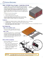
PSD to VN-Matrix Connection
1.
Using the supplied DC power cables, connect up to
12 VN-Matrix 200/225 or VN-Matrix 300/325 Series
encoder/decoder devices to the distribution assembly
as shown at right.
2.
Connect AC power to AC connector 1/2,
(VNM 12 PS), or 1/2 and 3/4 (VNM 12 PSR).
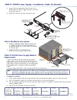
4.
Connect the two supply cables from the rear of the
VNM 12 PSD to the power supply terminals on the rear
of the PSU as shown.
5.
Replace the PSU terminal cover removed in step 1.
12V DC
RE
G
6A MA
X
I
IN
OU
T
DIGI
TA
L
AUDI
O
II
COM
1
OU
T
PC
PER
IPH
IN
COM
2
DVI-I
DV
I-I
12V D
C
RE
G
6A MA
X
I
IN
OU
T
DIGI
TA
L
AUDI
O
II
COM
1
OU
T
PC
PER
IPH
IN
COM
2
DVI-I
DV
I-I
12V DC
RE
G
6A MA
X
I
IN
OU
T
DIGI
TA
L
AUDI
O
II
COM
1
OU
T
PC
PERIPH
IN
COM
2
DVI-I
DV
I-I
12V DC
RE
G
6A MA
X
I
IN
OU
T
DIGI
TA
L
AUDI
O
II
COM
1
OU
T
PC
PERI
PH
IN
COM
2
DVI-I
DV
I-I
12V DC
RE
G
6A MA
X
I
IN
OU
T
DIGI
TA
L
AUDI
O
II
COM
1
OU
T
PC
PERIP
H
IN
COM
2
DV
I-I
DV
I-I
12V D
C
RE
G
6A M
AX
I
IN
OU
T
DIGI
TA
L
AUDI
O
II
COM
1
OU
T
PC
PERIP
H
IN
COM
2
DV
I-I
DV
I-I
12V DC
RE
G
6A MA
X
I
IN
OU
T
DIGI
TA
L
AU
DIO
II
COM
1
OU
T
PC
PERIP
H
IN
COM
2
DV
I-I
DV
I-I
12V DC
RE
G
6A M
AX
I
IN
OU
T
DIGI
TA
L
AUDI
O
II
COM
1
OU
T
PC
PERIP
H
IN
COM
2
DV
I-I
DV
I-I
DC Power Cables
(8 shown, 12 max.)
VNM 12 PS
VNM 12 PSR
VNM 12 PSD
VN-Matrix 200/225 or
VN-Matrix 300/325 Series
Encoder/Decoder
AC 3/4
AC 1/2
VNM 12 PS/PSR Power Supply Module
Replacement
There are two LEDs on the front panel of each power
supply module. The AC Power LED indicates whether AC
power input is present on the module. The DC power LED
lights green during normal operation or red, accompanied
by an audible alarm, to indicate a failed or overloaded
supply.
If a power supply module fails, it may be replaced without removing power.
NOTE:
Failed power supply modules in the VNM 12 PS can be replaced without removing AC power. However, if a
module fails, depending upon how many VN-Matrix devices are connected, DC power output may be shut
down. A failed module is identified and replaced the same as the VNM 12 PSR using the procedure below.
To replace a module:
1.
On the failed module, flip the front panel security latch up to release the module, then pull it from the frame.
2.
Push the replacement supply into the frame making certain it is on the mounting rails.
3.
Seat the supply by pressing it into the rear connector. Both the red AC and green DC indicators light when the power
supply is properly seated.
4.
Flip the security latch down to secure the module.
AC Power 1/2 Connector
(
VNM 12 PS and VNM 12 PSR)
16 A Supply Required
AC Power 3/4 Connector
(
VNM 12 PSR only)
16 A Supply Required
VNM 12 PS
VNM 12 PSR
Rear
VNM 12 PSD
Rear
Red
Connect positive cables.
(Terminal is NOT color coded.)
Black
Connect GND / RTN cables.
(Terminal is NOT color coded.)
Supply Cables
PSU D-sub
Connector
3/4
1/2
68-2002-01
Rev
B
06 11