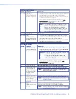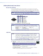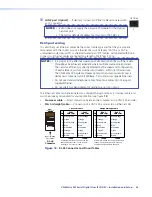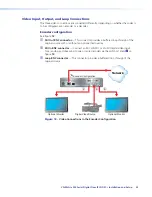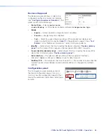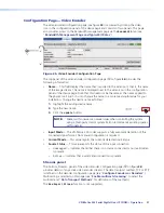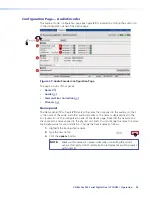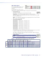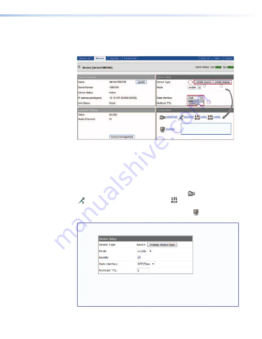
Configure the devices as encoders or decoders as follows.
1.
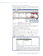
On the device list page, click anywhere on the row (except the Delete column) for the
device to be configured (item
a
in
figure 18
). This selects that device and displays the
device page (see figure
19
).
2
1
— or —
— or —
NOTE:
The icons displayed in this panel
are available only after you create
a source or display in step
3
.
Figure 19.
Configuring a Codec as a Source or Display
2.
In the Device Setup panel, click the Data Interface drop-down box (
a
in figure
19
) and
select either of the following as the cable to output or receive the video signal.
Cat6
(LAN port 1,
item
d
in figure
2
and on page 6)
SFP/Fibre
(LAN port 2,
item
e
in figure
2
and on page 6)
3.
In the Device Setup panel (
b
in figure
19
), configure the device as either an encoder or
decoder as follows:
Encoder
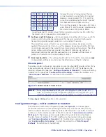
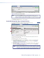
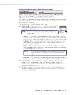
— Click the
create
source
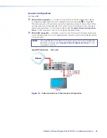
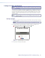
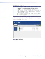
button. A video icon (
), an audio (ANC) icon
(
), and two forward error correction (FEC) icons (
) appear in the Configuration
box. Proceed to step
6
.
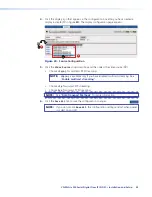
Decoder
— Click the
create
display
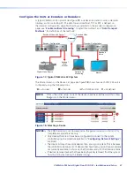
button. A display icon ( ) appears in the
Configuration box. Proceed to step
4
.
NOTE:
If a device is already configured, the device type is identified and the only
button available is “
change
device
type
”.
Click the button to display the create source and create display buttons,
and then perform step
3
.
If the device reports “
Device
is
streaming
data
”, log on to all decoders
that are connected to this encoder, one at at time, and clear the connection
(click
Please
select
a
source
on the display page (see
figure 20
on the
next page).
VN-Matrix 325 Serial Digital Over IP CODEC • Installation and Setup
28

