


5
5.
Connect a multimode fiber optic cable from the Output port of the transmitter to the Input port of the receiver (
The transmitter and receiver front panel Link LEDs will light steadily (
).
6.
If appropriate, choose a location and mount the transmitter and receiver
•
For rack mounting
, fasten the enclosure to the rack or rack shelf.
•
For furniture mounting
ZipClip 100 and 200 Mounting Installation
•
For table mounting
, attach the provided four rubber feet to the bottom of the unit and place it where desired.
7.
Power on the host computer. On the transmitter, the Host and Link LEDs (
) light when the computer recognizes the
transmitter, and when the transmitter and receiver are connected with each other.
8.
Connect up to two USB peripheral devices (such as a camera, keyboard, touchpanel or printer) to the receiver USB ports
(
).
The system is now ready to operate.
Front Panel Features
Transmitter – UCS FT 901
UCS FT 901
e
LINK
HOST
STATUS
POWER
12V
0.1A MAX
HOST
USB-C
SS 5G
Tx
OUTPUT
Rx
A
B
C
A
B
C
Receiver – UCS FR 902
e
UCS FR 902
LINK
STATUS
POWER
12V
1.6A MAX
DEVICES
INPUT
Tx
1
Rx
2
1.5 A
A
C
A
C
D
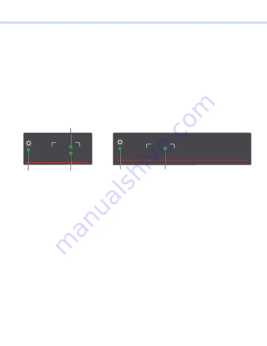
Figure 6.
Transmitter Front Panel
Figure 7.
Receiver Front Panel
A
Power LED
—
This green LED lights to indicate that the unit is receiving power.
B
Host LED
—
This green LED lights when the transmitter is powered, and communicating with the host PC.
C
Link LED
—
This green LED lights when the transmitter and receiver are connected by a fiber optic cable, receiving power.
6


