SW AR MX, SW AR MX HV, SW 6 Component • Operation
SW AR MX, SW AR MX HV, SW 6 Component • Operation
SW AR MX, SW AR MX HV, and
SW 6 Component Operation
4-3
blinking LED indicates the selected mode, you can release
the buttons.
• Front panel mode: Button 2
• Auto-switch mode: Button 3
• Auto-sequence mode: Button 4
Input selection from the front panel buttons is not
possible when the switcher is in auto-switch or
auto-sequence mode. However, all other front panel
operations function normally.
Front panel mode
In front panel mode, you can select the switcher input in
the following ways:
• Front panel buttons
• Optional remote control device (contact closure type) via
the manual remote connector (see “Attaching remote
control devices” on page 2-14)
• Optional host device/computer via the RS-232 port (see
“RS-232 Control” on page 4-7)
To select the input from the front panel, press the button
corresponding to the input number, and release it
immediately.
If you hold button 1 for too long, the mode is
indicated by a blinking LED 2 (indicating front
panel mode), and the input does not change.
Auto-switch mode
In auto-switch mode, the switcher selects the highest
numbered input that has sync pulses available on the sync
BNC connector. In the event that sync is lost on the
selected input, the switcher automatically switches to the
next higher input with sync available.
The auto-switch sync sensing circuitry monitors the "S"
(sync) BNC connector for all video formats except RGBHV.
The "V" (vertical sync) BNC connector is monitored if
RGBHV video format is used (SW AR MX HV models
only).
See page “Input cabling for auto-switching” on
page 2-10 for special cabling requirements.
This chapter applies to SW AR MX, SW AR MX HV, and
SW 6 Component switchers only. For SW AR
xi
and
SW AR HV
xi
operation information, see chapter 3.
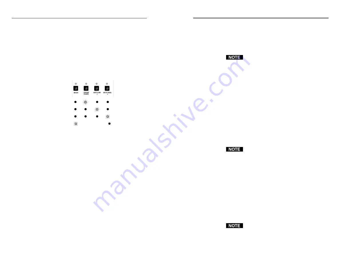
Operating Modes
SW AR MX, SW AR MX HV, and SW 6 Component
switchers operate in three modes: front panel mode, auto-
switch mode, and auto-sequence mode. To determine the
current mode, press and hold front panel button #1 until
LED #2, 3, or 4 begins blinking. The blinking LED
identifies the mode, as shown below.
Mode:
Front panel
Auto-switch
Auto-sequence
Symbols:
= blinking LED,
= LED in Off state.
Regardless of the mode the switcher is in, you can select the
mode in the following ways:
• Through the front panel buttons (see below)
• Through the manual remote connector (see “Attaching
remote control devices” on page 2-14)
• From a host device/computer connected to the switcher’s
RS-232 port (see “RS-232 Control” on page 4-7)
Selecting the mode from the front panel
The front panel has four or six buttons, each with an LED
indicator above it. Buttons 1 and 2 (SW 2 AR MX), buttons
1 through 4 (SW 4 AR MX and SW 4 AR MX HV), or
buttons 1 through 6 (SW 6 AR MX, SW 6 AR MX HV, and
SW 6 Component) select the switcher input in front panel
mode. Buttons 1 through 4 are also used to select the mode.
See the mode sections beginning on the next page for
information on selecting inputs when the switcher is in
each mode.
To select the mode from the front panel, press and hold
button 1 until LED 2, 3, or 4 begins blinking, then press and
hold the button corresponding to the mode you want (see
the next page) while continuing to press button 1. When a
4-2
1
2
3
4
Artisan Technology Group - Quality Instrumentation ... Guaranteed | (888) 88-SOURCE | www.artisantg.com


