

2
© 2018 - 2020 Extron Electronics All rights reserved.
All trademarks mentioned are the property of their respective owners.
Worldwide Headquarters: Extron USA West, 1025 E. Ball Road, Anaheim, CA 92805, 800.633.9876
SMK 1 • Installation Guide (Continued)
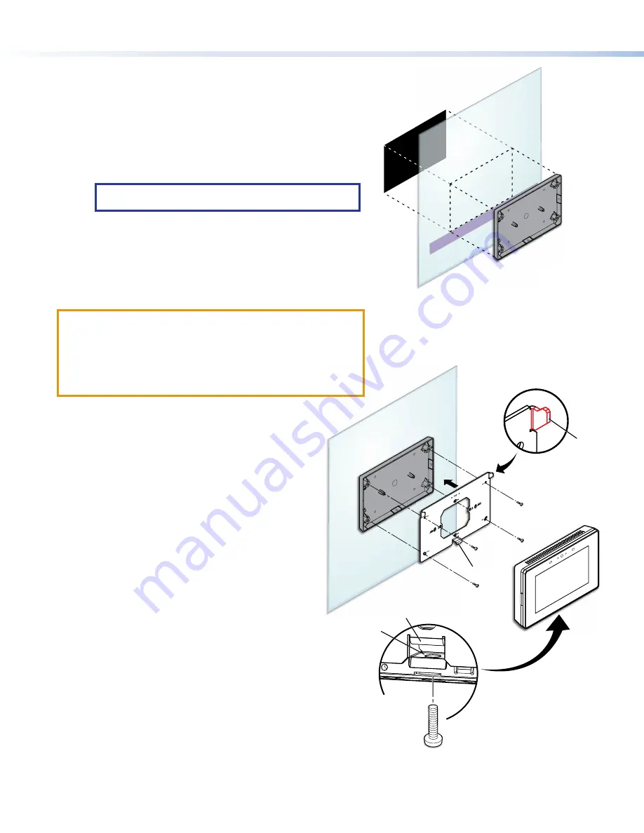
4.
Hold the SMK 1 at a slight angle with the top tilting forward
and carefully align the bottom inner edge of the SMK 1 with the
painter’s tape (see figure 3,
1
).
5.
Press the SMK 1 firmly against the glass surface.
6.
Remove the painter’s tape.
7.
(Optional) The rear overlay cover can be applied to the inside glass
surface (
2
) to hide any air bubbles that were trapped between the
SMK 1 and the outside glass surface.
a.
Remove the paper backing from the cover overlay.
TIP:
Wet your fingers to prevent them from sticking to the
adhesive patch.
b.
Center the cover overlay behind the SMK enclosure.
c.
Use a credit card or similar flat edge to remove any air
bubbles.
e
e
e
Mounting Plate
TLP Pro 525M
SMK 1
Back View
4
4
4
3
3
3
5
5
5
5
5
5
6
6
6
7
7
7
Figure 4.
Mounting the TLP Pro 525M
figure 4
Mounting the TLP Pro 525M
ATTENTION:
•
Do not power on the touchpanels until you have read the
Attention in the Power supply section of the TLP Pro 525, 725,
and 1025 Series User Guide.
•
Ne branchez pas les écrans tactiles avant d’avoir lu la mise
en garde du TLP Pro 525, 725, et 1025 Series dans la section
« sources d’alimentation » du User Guide.
1.
Run the provided flat Ethernet cable from a Power
over Ethernet injector to the SMK 1 (see the
TLP Pro 525, 725, and 1025 Series User Guide
). Pass
the cabe through the touchpanel mounting plate.
2.
Fasten the mounting plate to the SMK 1 using the
four M3 screws provided (see figure 4,
3
). Use the
holes, marked
WALL
, closest to each corner of the
mounting plate.
Ensure the cable passes through the gap left by
removing the knockout (see
previous page).
3.
Attach the cable to the LAN/PoE input on the
TLP Pro 525M rear panel (see the
TLP Pro 525, 725,
and 1025 Series User Guide
).
4.
The mounting plate has two hooks (
4
), one on each
of the top corners. Position the TLP Pro 525M so that
these hooks fit into the slots at the top of the rear
panel of the touchpanel (see the
TLP Pro 525, 725,
and 1025 Series User Guide
).
5.
Slide the TLP Pro 525M down slightly so that the
hooks are seated securely in the slots.
6.
The tongue at the bottom of the mounting plate (
5
)
sits in the groove in the bottom of the touchpanel
(see inset,
6
). Fasten the touchpanel to the
mounting plate by tightening the lock screw (
7
).
1
1
1
2
2
2
e
e
Figure 3.
Attaching the SMK 1 to the Glass
68-3112-01 Rev. B
01 20


