3
j
Down (
<
) button and LED — The
<
button decreases the audio gain for a selected input. Press and release the button to
decrease the gain by 1 dB or press and hold the button to decrease the gain by 3 dB per second until the button is released or
the lower limit is reached.
NOTES:
•
On 8-output switchers, this button and LED are secondary functions of the Output 7 button and LED.
•
The
<
LED flashes once in Audio Setup mode to indicate each 1 dB decrease in the input audio gain (see “
and Adjusting the Audio Input Gain
” on page 4. The
<
LED lights steadily in Audio Setup mode to indicate that the
adjustment has reached the maximum attenuation (-18 dB).
k
Up (
>
) button and LED — The
>
button increases the gain for a selected input. Press and release the button to increase the
audio level by 1 dB or press and hold the button to increase the audio level by 3 dB per second until the button is released or
the upper limit is reached.
NOTES:
•
On 8-output switchers, this button and LED are secondary functions of the Output 8 button and LED.
•
The
>
LED flashes once in Audio Setup mode to indicate each 1 dB increase in the input audio gain (see “
and Adjusting the Audio Input Gain
” on page 4). The
>
LED lights steadily in Audio Setup mode to indicate that
the adjustment has reached the maximum gain (+10 dB).
Operation
Powering Up
Plug in the switcher to apply power. The switcher performs a self-test that sequences the front panel LEDs. After the self-test, video
and audio are selected and the configuration and audio settings are the same as they were when power was removed.
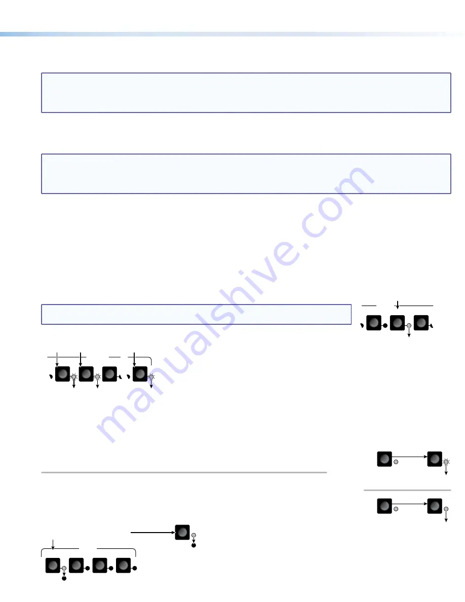
Creating a Tie
1.
Press and release the I/O button to select (lit) or deselect (unlit) the Video LED, audio LED, or both as desired.
2.
Press and release the desired input button.
6
5
4
INPUTS
Press and release the Input 5 button.
The Input 5 LED lights to
indicate that input 5 is selected.
NOTE:
If you wait for the 5-second input/output button timeout to occur after either step 2
or step 3, the entire set of ties is cancelled.
3.
Press and release one or more desired output buttons.
5
4
3
8
OUTPUTS
Press and release the Output 3, 4, and 8 buttons.
The LEDs blink to indicate that the selected
input will be tied to these outputs.
4.
Press and release the Enter button. The LEDs for the selected input and the selected outputs light steadily for
approximately 1 second to indicate the tie and then turn off.
Saving or Recalling a Preset
1.
To save a preset: Press and hold the Preset button until the Preset LED starts blinking.
PRESET
PRESET
PRESET
PRESET
Save a preset
Recall a preset
Press and
hold
.
2 seconds
Preset LED blinks.
Release the Preset button.
Press and release.
Preset LED lights.
To recall a preset: Press and release the Preset button.
2.
Press the desired input or output button. The LEDs for the selected input button and
Preset button remain lit for 1 second to indicate the preset and then turn off.
PRESET
2
4
1
INPUTS
3
Press and release the Input 1 button
to select
preset 1
to save or recall.
Preset 2 Preset 3 Preset 4
The Preset LED
and Input 1 LED
light for 1 second
then turn off.


