background image

LockIt HDMI Cable Lacing Bracket

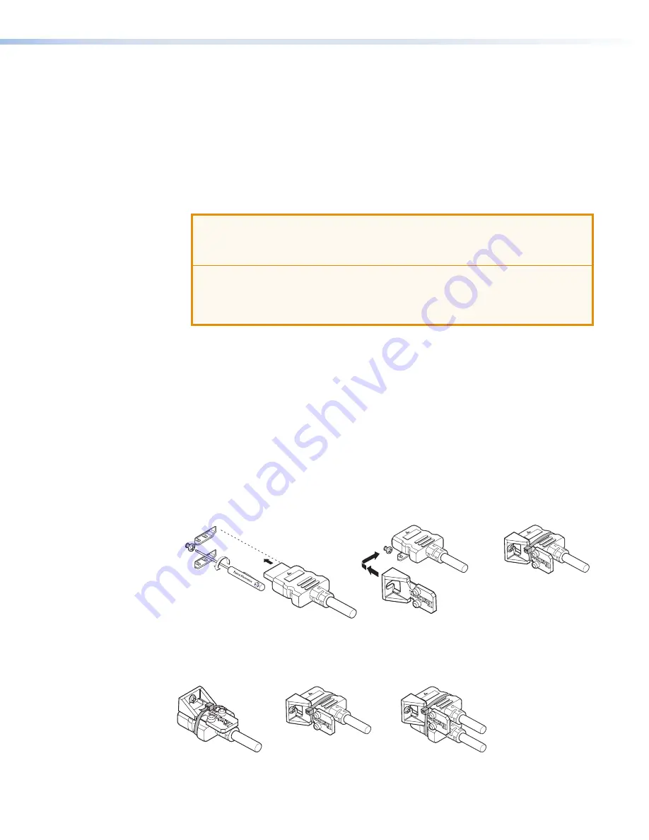
The included LockIt lacing brackets secure the HDMI cables to the rear panel connectors 
as shown in figure 8, below. The configuration of the HDMI connectors and supporting 
fasteners on the MPS 601 rear panel require using a top mount (HDMI output, see figure 9,  
Top) and a stacked side mount (HDMI inputs 3 and 4, and inputs 5 and 6) installation to 
secure the four inputs and single output.

To secure a single HDMI cable in HDMI inputs 3 and 5:

1. 

Loosen the HDMI connection mounting screw from the panel enough to allow LockIt 
lacing bracket placement (see figure 8, 

1

). 

ATTENTION:


• 

Do not remove the HDMI connection mounting screw.

• 

Ne retirez pas la vis de montage de la connexion HDMI. 

• 

Do not overtighten the HDMI connector mounting screw. The shield it fastens to 
is very thin and can easily be stripped.

• 

Ne serrez pas trop la vis de montage du connecteur HDMI. Le blindage auquel 
elle est attachée est très fin et peut facilement être dénudé.

2. 

Plug the HDMI cable into the panel connection (

2

).

3. 

Place the LockIt lacing bracket on the screw and against the HDMI connector (

3

), then 

tighten the screw to secure the bracket.

4. 

Loosely place the included tie wrap around the HDMI connector and LockIt lacing 
bracket (

4

). Hold the connector securely against the lacing bracket and tighten the tie 

wrap, then remove excess length.

To secure two HDMI cables in HDMI inputs 3 and 4 or inputs 5 and 6:

1. 

Loosen the HDMI connection mounting screw from the panel near HDMI input 4 
enough to allow LockIt lacing bracket placement. 

2. 

Insert both HDMI cables into the panel.

3. 

Use a single LockIt lacing bracket to the side of the cable. 

4. 

Secure both with the tie wrap as shown in the stacked configuration in figure 8.


4

3

3

2

3

3

Side

Stacked

3

Top

HDMI

1

2

3

4

Figure 8. 

Lockit Lacing Bracket Installation

A single LockIt bracket can be used to secure two HDMI connectors in a stacked 
configuration as shown in figure 9.

4

3

3

2

3

3

Side

Stacked

3

Top

HDMI

1

2

3

4

Figure 9. 

Lockit Lacing Bracket Examples


MPS 601 • Installation

9

Summary of Contents for MPS 601

Page 1: ...User Guide MPS 601 HDMI Switchers Media Presentation Switcher 68 2454 01 Rev D 01 19 ...

Page 2: ...ériel Pour en savoir plus sur les règles de sécurité la conformité à la réglementation la compatibilité EMI EMF l accessibilité et autres sujets connexes lisez les informations de sécurité et de conformité Extron réf 68 290 01 sur le site Extron www extron com Istruzioni di sicurezza Italiano AVVERTENZA Il simbolo se usato sul prodotto serve ad avvertire l utente della presenza di tensione non iso...

Page 3: ... Systems Inc or Extron Electronics see the current list of trademarks on the Terms of Use page at www extron com Registered Trademarks Extron Cable Cubby ControlScript CrossPoint DTP eBUS EDID Manager EDID Minder Flat Field FlexOS Glitch Free Global Configurator Global Scripter GlobalViewer Hideaway HyperLane IP Intercom IP Link Key Minder LinkLicense LockIt MediaLink MediaPort NetPA PlenumVault P...

Page 4: ...nstalled and used in accordance with the instruction manual may cause harmful interference to radio communications Operation of this equipment in a residential area is likely to cause interference This interference must be corrected at the expense of the user NOTE For more information on safety guidelines regulatory compliances EMI EMF compatibility accessibility and related topics see the Extron ...

Page 5: ...r or device responses used in this guide the character 0 is used for the number zero and O is the capital letter o Computer responses and directory paths that do not have variables are written in the font shown here Reply from 208 132 180 48 bytes 32 times 2ms TTL 32 C Program Files Extron Variables are written in slanted form as shown here ping xxx xxx xxx xxx t SOH R Data STX Command ETB ETX Sel...

Page 6: ......

Page 7: ...8 Starting the Software 19 Device Discovery Panel 20 Offline Device Preview 21 Using the Software and Device Menus 22 Device Menu 22 Software Menu 26 Navigating the PCS Application 28 AV Controls Panel 28 Configuration Pages 28 Input Output Configuration 29 EDID Minder Page 30 Image Settings Page 33 Audio Config Page 34 General Settings Page 35 Remote Communication and Control 37 Connection Option...

Page 8: ...MPS 601 Contents viii ...

Page 9: ...or digital and analog sources It offers four HDCP compliant HDMI inputs and two RGB video inputs with analog stereo audio RGB video and analog audio are digitized and switched through the HDMI output The MPS 601 features two Extron exclusive technologies EDID Minder which maintains continuous EDID communication between connected devices and Key Minder which continuously authenticates and maintains...

Page 10: ...rmance parameters HDMI to DVI interface format correction Automatically reformats HDMI source signals for output to a connected DVI display Automatic input cable equalization to 50 feet 15 meters at 1080p 60 Hz with 8 bit color when used with Extron HDMI Pro Series cable Actively conditions incoming HDMI signals to compensate for signal loss when using long cables low quality cables or source devi...

Page 11: ...ASCII code commands that allow quick and easy programming Contact closure remote control with tally output Used for remote selection of an input channel 5 VDC is provided to light an LED to indicate the current input Rack mountable 1U half rack width metal enclosure LockIt HDMI Cable Lacing Brackets Energy efficient external universal power supply Provides worldwide compatibility low power consump...

Page 12: ...HDMI HDMI RS 232 G C 1 3 5 2 4 6 T T C G T C G G C T T C G T V C G Tx Rx G OUTPUT REMOTE Figure 2 MPS 601 Rear Panel Power and Input Connections Output Connection Control Device Connections A DC power connector B Two configurable analog 15 pin HD VGA connectors C Two female 3 5 mm TRS connectors lettered A and B on the rear panel corresponding to the two RGBHV video inputs D Four female HDMI conne...

Page 13: ...térieur d un placard d une estrade ou d un bureau The installation must always be in accordance with the applicable provisions of National Electrical Code ANSI NFPA 70 article 725 and the Canadian Electrical Code part 1 section 16 The power supply shall not be permanently fixed to building structure or similar structure Cette installation doit toujours être en accord avec les mesures qui s appliqu...

Page 14: ...ht showing Contact In and Tally Out connector wiring NOTE Do not tin the leads Tinned wires are not as secure in the connector and could be pulled out G V Port 3 pole 3 5 mm captive screw connector The V V V Do not tin the wires three pins constantly output 5 VDC 200 mA total shared between pins to provide power for external tally LEDs see the image on the right showing V connector wiring NOTE Do ...

Page 15: ...ct Closure Application Diagram with Show Me Cables A MAX POWER 12V 1 2 B A 3 4 5 6 INPUTS MPS 601 CONTACT IN TALLY OUT HDMI RGBHV HDMI HDMI RS 232 G C 1 3 5 2 4 6 T T C G T C G G C T T C G T V C G Tx Rx G OUTPUT REMOTE MPS 601 Tally Contact Closure Power Supply 12V 1A Display HDMI Video and Embedded Audio Laptop 1 Video 1 Audio A Video 2 Audio B Blu ray Player Laptop 2 Audio Video Audio Video Tall...

Page 16: ...306 A MAX POWER 12V 1 2 B A 3 4 5 6 INPUTS MPS 601 CONTACT IN TALLY OUT HDMI RGBHV HDMI HDMI RS 232 G C 1 3 5 2 4 6 T T C G T C G G C T T C G T V C G Tx Rx G OUTPUT REMOTE Two Contact Closure Switch AAP PC Solder Cups Normally Closed NC Normally Open NO Common Ground C LED LED MPS 601 Resistor R NOTE Determine and select the appropriate current limiting resistor if needed Many button switches have...

Page 17: ...tachée est très fin et peut facilement être dénudé 2 Plug the HDMI cable into the panel connection 2 3 Place the LockIt lacing bracket on the screw and against the HDMI connector 3 then tighten the screw to secure the bracket 4 Loosely place the included tie wrap around the HDMI connector and LockIt lacing bracket 4 Hold the connector securely against the lacing bracket and tighten the tie wrap th...

Page 18: ...iate adapters sources see Connections on page 4 4 Connect the HDMI output to a compatible display device see Connections 5 For analog audio input connect audio sources to the audio inputs corresponding to the RGBHV video inputs see Connections 6 Connect a control PC or control device to the switcher using a The rear panel RS 232 port and a 3 pole captive screw connector see Remote Control Port RS ...

Page 19: ... to the HDMI output Only one of the six inputs can be selected at a time D Input signal LEDs Six green LEDs The LEDs for RGB inputs 1 and 2 light when horizontal sync is detected on the input The LEDs for HDMI inputs 3 to 6 light when TMDS clock activity is detected on the input NOTE If a connected HDMI source is HDCP encrypted the HDMI signal LED does not light until HDCP is authenticated If HDCP...

Page 20: ...o muted Mode 1 Default When each RGBHV input has an associated audio input the associated audio input follows the selected input Audio input A follows input 1 yellow box in figure 11 Input 1 selected RGBHV 1 video and audio input A switch to the HDMI output Audio input B follows input 2 green box in figure 11 Input 2 selected RGBHV 2 video and audio input B switch to the HDMI output Inputs 3 throu...

Page 21: ...e output When input 3 or input 5 is selected the selected HDMI video signal switches to the output If embedded digital audio is present on the selected HDMI input it switches to the output If digital audio is not present analog audio input A switches to the output The priority selection is embedded digital audio see Autodetect for Audio on page 14 Audio input B is grouped with inputs 2 4 and 6 Inp...

Page 22: ...o the highest active input number Automatically switches to the highest numbered input with active video Priority to the lowest active input number Automatically switches to the lowest numbered input with active video NOTE When auto input switching is enabled and if video is absent from all inputs input 1 is selected Front Panel Lockout Executive Mode Executive mode provides security from an accid...

Page 23: ...splay EDID and store it one of four user slots Whether stored automatically or manually the EDID file is written to internal memory for each input Automatic Mode If an output display has never been connected a default EDID file is placed on the RGB and HDMI inputs according to the following table Input Group Default EDID RGBHV 1920x1080 60 Hz HDMI 1080p 60 Hz 2 Ch PCM audio When a display is conne...

Page 24: ...PC VGA N A 10 1440 x 900 60 Hz PC VGA N A 11 1600 x 900 60 Hz PC VGA N A 12 1600 x 1200 60 Hz PC VGA N A 13 1680 x 1050 60 Hz PC VGA N A 14 1920 x 1080 60 Hz PC VGA N A 15 1920 x 1200 60 Hz PC VGA N A 16 2048 x 1080 60 Hz PC VGA N A 17 800 x 600 60 Hz PC DVI N A 18 1024 x 768 60 Hz PC DVI N A 19 1280 x 720 60 Hz PC DVI N A 20 1280 x 768 60 Hz PC DVI N A 21 1280 x 800 60 Hz PC DVI N A 22 1280 x 102...

Page 25: ...h 54 1080p 50 Hz HDTV HDMI 2 Ch 55 1080p 60 24 Hz HDTV HDMI 2 Ch 56 1080p 60 Hz HDTV HDMI 2 Ch 57 4K UHD 30 Hz HDTV HDMI 2 Ch 58 720p 50 Hz HDTV HDMI Multi Ch 59 720p 60 Hz HDTV HDMI Multi Ch 60 1080i 50 Hz HDTV HDMI Multi Ch 61 1080i 60 Hz HDTV HDMI Multi Ch 62 1080p 50 25 Hz HDTV HDMI Multi Ch 63 1080p 50 Hz HDTV HDMI Multi Ch 64 1080p 60 24 Hz HDTV HDMI Multi Ch 65 1080p 60 Hz HDTV HDMI Multi C...

Page 26: ...avigating the PCS Application Configuration Pages The graphical interface includes the same functions as those on the device front panel with additional features available only using the software The control software is compatible with Microsoft Windows operating systems The software is available on the Extron website Installing the Software 1 On the Extron website enter PCS in the search text box...

Page 27: ...to the Device Discovery page The MPS 601 supports USB connection only however all devices supported by PCS are listed in the Device Discovery panel see figure 13 Figure 13 Start up Page NOTE PCS versions prior to 2 0 do not have the Device Discovery feature Download the latest version of PCS see Installing the Software on page 18 The configuration screens and panels can be viewed offline however o...

Page 28: ...tified and sorted by model IP address device name or connection method Figure 14 Device Discovery Panel To sort the list of available devices 1 Click the Device Discovery tab see figure 14 1 2 Click the desired column heading 2 to sort the category in ascending or descending order To connect to a device 1 Click the Device Discovery tab 1 2 Select the desired device 3 the device row is high lighted...

Page 29: ...rt up tab see figure 15 select Down arrow New Configuration File 1 Figure 15 Configuration Drop down Menu The New Configuration File dialog box opens see figure 16 2 2 1 1 1 IN1606 IN1608 IN1608 IPCP MA 100 MPS 601 MPS 602 MA MPS 602 SA PVS 405D Device Models Figure 16 New Configuration File Dialog Box MPS 601 Selected 2 Select the desired device model from the Device Models list 1 3 Click Configu...

Page 30: ...ation options The main screen is divided into the AV Controls panel 3 and ribbon bar 4 Device Menu Click the down arrow beside the device name to access the Device drop down menu see figure 18 The menu contains options for connecting disconnecting changing the device name resetting the device updating firmware accessing the MPS 601 Help file and viewing software version information Figure 18 Devic...

Page 31: ...Part Number Extron part number of the MPS 601 version 2 Model Name Model name and version 3 Model Description Media Presentation Switcher 4 Firmware Version Currently active firmware version 5 The Device Name tab see figure 20 provides the following functionality Figure 20 Hardware Settings Dialog Box Device Name Enter a Device Name This is the name listed in the Device Discovery table of PCS see ...

Page 32: ...e Firmware Dialog Warning 2 Click Continue 1 to proceed The Update Firmware dialog continues see figure 22 Figure 22 Update Firmware Dialog Select Firmware File 3 Click Browse 1 4 Navigate to the firmware file location and select the file Valid firmware files have an S19 file extension 5 Click Open The firmware file is selected and the Update Firmware dialog reopens with the file path see figure 2...

Page 33: ... see figure 18 4 on page 22 to open the MPS 601 specific Help file The Help file contains configuration and operating instructions that apply to the MPS 601 Device Menu About This Module This option 5 contains the device module part number and firmware version of the connected device 1 From the Device drop down list select About This Module A dialog box opens see figure 25 Figure 25 About This Mod...

Page 34: ... Menu to open the list of options see figure 27 1 2 Select Show Expanded Device Tabs 2 The device tab now includes the active connection see figure 27 Figure 27 Expanded Device Tab Software Settings This option resets all disabled confirmation dialogs to the default settings 1 Click Software Menu Software Settings see figure 26 3 The Software Settings dialog opens see figure 28 Figure 28 Software ...

Page 35: ...e 29 Figure 29 About This Module Dialog Box Part Number is the Extron part number of the MPS 601 module in PCS Version is the specific version of the MPS 601 module Click Close to close the dialog Exit This option disconnects PCS from connected devices and closes the application 1 Click Software Menu Exit see figure 26 7 The Exit dialog box opens see figure 30 Figure 30 Exit Dialog Box 2 If necess...

Page 36: ...ontrols panel 3 lets you select between the connected input sources and also mute output audio video or both The selected mute button turns red to indicate a muted source audio is muted in figure 33 Click a red mute button to unmute the source The button returns to gray Figure 33 AV Controls Panel Mute Buttons NOTE The AV Controls panel can be hidden or revealed on any page by clicking on the arro...

Page 37: ...l indicator in the AV Controls panel lights green when a signal is present on the corresponding input and orange when there is no signal present Input This number corresponds to the input number on the rear panel Signal Type Indicates the source signal type RGBHV The input is an analog signal Digital Video The input is an HDMI or DVI signal HDCP Status This column indicates the HDCP signal status ...

Page 38: ...anages the EDID information between the switcher and one or more input sources Click the EDID Minder icon on the Global Navigation Bar to open the page see figure 35 1 1 1 2 2 3 3 4 4 5 5 6 6 Figure 35 EDID Minder Page The EDID Minder page is divided into five panels 2 Filter Select from the drop down lists in each category to limit the EDIDs shown in the three EDID screens 3 Favorites Drag and dr...

Page 39: ...PCM 2Ch 2 channel audio Multi Ch Multi channel audio LPCM 2Ch Auto 2 channel audio Multi Ch Auto Multi channel audio NOTE If an analog custom EDID file is assigned to a digital input or a digital custom EDID file assigned to an analog input the display may not appear correctly Filtering Available EDID Use the Filter panel see figure 35 2 on the previous page to limit the number of available EDID d...

Page 40: ...sign an EDID to all inputs 1 From the Favorites Connected Outputs or Available EDID panel on the left click the desired EDID The selection highlights 2 2 From the Inputs panel on the right click Assign 3 NOTE Checked or unchecked inputs are ignored and the EDID is assigned to all inputs To match the selected inputs to the current output resolution Matching the output resolution is the default valu...

Page 41: ...g indicates it is the default value for the applied video signal 2 Horizontal Start Defines the number of pixels from the start of the horizontal line where active video begins 3 Vertical Start Defines the number of lines from the start of the vertical line where active video begins 4 Total Pixels The total number of pixels in a horizontal line including blanking on both sides of the active video ...

Page 42: ...ith the analog inputs When input 1 or input 2 is selected video from the selected input and audio from audio input A is routed to the HDMI output Audio input B is disabled When inputs 3 4 5 or 6 are selected the selected HDMI video and embedded audio is routed to the HDMI output 4 Mode 3 Audio input A is grouped with inputs 1 3 and 5 Audio input B is grouped with inputs 2 4 and 6 When input 1 is s...

Page 43: ...gure 40 1 1 1 2 2 3 3 4 4 5 5 Figure 40 Device Settings Page Hardware Settings Click this button 2 to access the same information available from the device tab see Settings Hardware Settings Dialog Box on page 23 Front Panel Lockout Executive Mode Panel The Front Panel Lockout panel 3 contains options for enabling or disabling the front panel lockout mode When enabled executive mode provides secur...

Page 44: ...input with active video Priority to the lowest active input number Automatically switches the input to the lowest numbered input with active video Visual Indication of Mute Status panel 5 When an input uses the Extron Show Me cable or uses other Contact In Tally Out connections the tally indicator can be configured to show the current state of the input To configure the indicator select Disabled A...

Page 45: ... switcher responses The RS 232 connector on the PC is a female 9 pin D with the following pin designations Pin RS 232 Function Description 1 No connection 2 Tx Transmit data 3 Rx Receive data 4 No connection 5 Gnd Signal ground 6 7 No connection 8 9 No connection The protocol for the serial port is 9600 baud no parity 8 data bits 1 stop bit no flow control Commands and responses for programming th...

Page 46: ...IG SIGNAL INPUTS INPUTS OUTPUT 1 2 3 4 5 6 HDCP 1 2 3 4 5 6 AUTO SWITCH MPS 601 Front Panel WiFi 1 2 3 4 USB Cable Type A USB Mini Type B USB USB Ports PC Figure 41 Connecting a PC to the MPS 601 Front Panel USB Port 2 If this is the first time an Extron product is connected to the PC the Found New Hardware Wizard dialog opens see figure 42 The first screen offers to connect to Windows Update to s...

Page 47: ...river to the same USB port 6 When the Completed dialog box opens click Finish to close the wizard 7 Configure the MPS 601 as required Host to MPS Communications The MPS switcher accepts Simple Instruction Set SIS commands through the RS 232 and USB configuration port SIS commands consist of one or more characters per command field They do not require special characters to begin or end the command ...

Page 48: ...r signal type E22 Busy Command and Response Table Using the Command and Response Table The command and response table is shown on the following pages Lower case characters are acceptable in the command field only where indicated Symbols are used throughout the table to represent variables in the command and response fields Symbol definitions are shown below Command and response examples are shown ...

Page 49: ...ult 1 Off when muted 2 Blink when muted X1 Name is a text string of up to 24 alpha numeric characters and a minus sign or hyphen No blank or space characters are permitted No distinction between upper and lower case The first letter must be a letter and the last character must not be a minus sign or hyphen Default MPS 601 X2 Input HDCP status 0 not connected 1 HDCP encrypted default 2 not HDCP enc...

Page 50: ...page 12 View input audio mode EAMOD X1 Input auto switching Disable input auto switch E0AUSW Ausw0 Manual input switching default Priority to highest active input E1AUSW Ausw1 Priority to lowest active input E2AUSW Ausw2 View input auto switch setting EAUSW X1 KEY X Input number Inputs 0 through 6 for single input addressing 0 deselect all X Status 0 Off disable default 1 On enable X Signal status...

Page 51: ...al start value EX X3 VSRT VsrtX X3 Set the vertical start value X3 for input X Increment vertical start value EX VSRT VsrtX X3 Decrement vertical start value EX VSRT VsrtX X3 View vertical start value EX VSRT X3 View the vertical start value X3 of input X HDCP Management Set HDCP authorization per input E EX X HDCP HdcpE X X X HDMI inputs 3 6 only Set HDCP authorization for all inputs EEX HDCP Hdc...

Page 52: ... status X Audio mute status X Query model name 1I MPS 601 Query part number N 60 1337 01 Pno60 1337 01 Verbose mode 2 3 KEY X Input number Inputs 0 through 6 for single input addressing 0 deselect all X Mute status 0 Off or disabled 1 on or enabled X1 Executive mode status 0 Unlocked or disabled default 1 Locked or enabled X1 Auto input switching mode 0 Disabled manual switching default 1 On or en...

Page 53: ...d EDID of input in hex format ERX EDID X2 View EDID native resolution ENX EDID X Read native resolution and refresh rate from currently selected EDID Example 1080p 60 00Hz KEY X Video Input Inputs 1 through 6 for single input addressing X EDID memory slot number From lookup table see User Assigned EDID Mode on page 16 1 66 Factory EDIDs 67 Output autodetect 68 71 User loaded EDID slots Default Vid...

Page 54: ...ti unit rack assembly the operating ambient temperature of the rack environment may be greater than room ambient temperature Therefore install the device in an environment compatible with the maximum ambient temperature Tma 122 F 50 C specified by Extron 2 Reduced air flow Install the equipment in a rack so that the amount of air flow required for safe operation of the equipment is not compromised...

Page 55: ... w Nylon Captive Cap Washer Figure 44 Rack Mounting the Switcher Table or Wall Mounting The table and wall mounting brackets extend approximately 1 4 inch 6 4 mm above the top surface of the switcher enclosure allowing for an air space between the enclosure and the surface Follow the instructions provided with your mounting choice Mounting Screws 2 Plcs Each Side Optional Furniture Mounting Bracke...

Page 56: ...el RS 232 port 3 In the Port Configuration panel 2 configure the port settings shown with the correct protocol settings at right 4 To automatically connect to the MPS 601 select Connect on startup 3 5 Click OK 4 to start using the program You are now ready to enter commands See the DataViewer help file for more information about program operation To connect via USB 1 Click the desktop Dataviewer i...

Page 57: ...Downloads tab and locate the most recent firmware file release notes and firmware update instructions Save these files on your computer hard drive noting the file path of the folder where the files are saved To access Firmware Loader 1 From the Windows start menu select All Programs Extron Firmware Loader Firmware Loader The Add Device dialog box opens see figure 46 1 1 2 2 3 3 4 4 5 5 6 6 7 7 Fig...

Page 58: ...centage of completion MPS 601 60 1377 01 2 01 0001 2 05 0001 1 1 2 2 Figure 48 Firmware Loader Progress Bar After uploading the firmware file the program verifies the file successfully uploaded When the verification is finished the update is completed see figure 49 1 and 2 1 1 2 2 3 3 MPS 601 60 1377 01 2 01 0001 2 05 0001 Figure 49 Firmware Loader Completed Firmware Update 9 From the File drop do...

Page 59: ... United Arab Emirates Dubai This Limited Warranty does not apply if the fault has been caused by misuse improper handling care electrical or mechanical abuse abnormal operating conditions or if modifications were made to the product that were not authorized by Extron NOTE If a product is defective please call Extron and ask for an Application Engineer to receive an RA Return Authorization number T...

Reviews: