


© 2006 Extron Electronics. All rights reserved.
Extron Electronics, USA
1230 South Lewis Street
Anaheim, CA 92805
USA
714.491.1500
Fax 714.491.1517
Extron Electronics, Europe
Beeldschermweg 6C
3821 AH Amersfoort
The Netherlands
+31.33.453.4040
Fax +31.33.453.4050
Extron Electronics, Asia
135 Joo Seng Road, #04-01
PM Industrial Building
Singapore 368363
+65.6383.4400
Fax +65.6383.4664
Extron Electronics, Japan
Kyodo Building
16 Ichibancho
Chiyoda-ku, Tokyo 102-0082 Japan
+81.3.3511.7655
Fax +81.3.3511.7656
www.extron.com
Setup Guide
68-1288-01
A
07 06
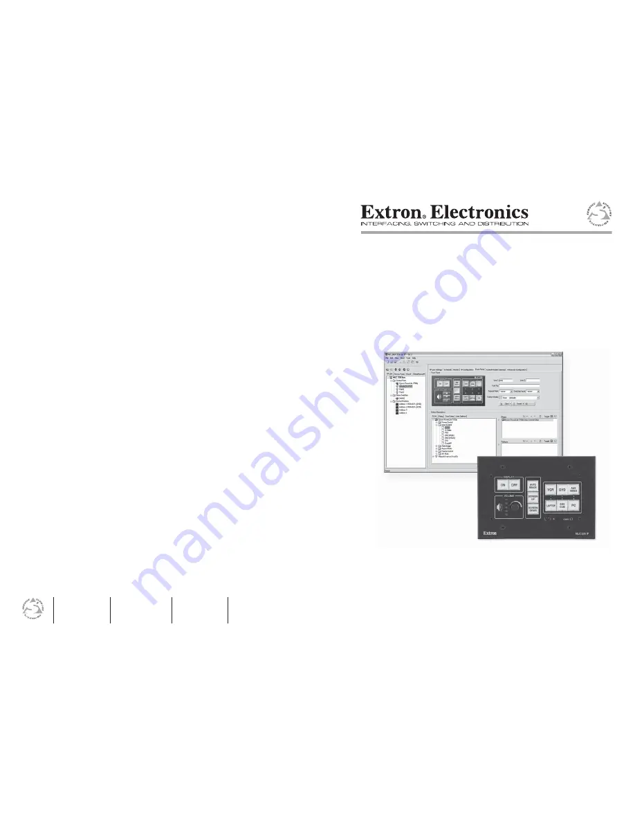
MLC 226 IP Series
MediaLink
™
Controllers


