
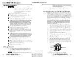

IR Link • Installation and Operation
Installation and Operation, cont’d
IR Link
A
Appendix A
Specifications, Part Numbers,
and Dimensions
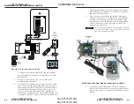
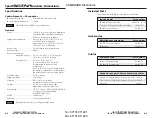
Specifications
Included Parts
Accessories
Cables
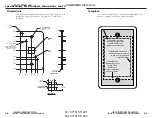
Dimensions
Template
2-12
Testing/Troubleshooting
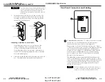
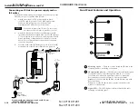
Before installing the IR Link into the wall or furniture, test the
system to make sure that the connections are correct and the
IR Link is working correctly.
1.
Connect the cables between the MediaLink Controller or
MediaLink Switcher and the IR Link, and connect the
Controller or Switcher to a power source;
or
connect the IR Link’s external power supply to a power
source and connect the IR-controllable Extron device to a
power source.
Make sure that only one IR Link is connected to the
controller, switcher, or power supply.
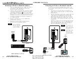
2.
Aim the Extron device’s remote control at the IR Link and
press one of the buttons. Watch the IR Link’s Signal LED,
and observe the Extron device or the display connected to
the device.
2A
If the Signal LED does not light when the IR remote
control’s button is pressed, check the captive screw
connector wiring at the MediaLink Controller or
MediaLink Switcher (if applicable) and at the
IR Link’s connectors.
If the conductor assignments are not correct at both
ends of the cable, the IR Link will not turn on, and
circuits may be damaged if power is applied to the
wrong pin.
2B
If power is present at the MediaLink Controller/
Switcher/power supply and at the IR Link, the
Signal LED lights when the remote control’s button is
pressed, but the MediaLink Controller, MediaLink
Switcher, or other Extron device does not respond as
expected, verify that the device has been set up or
programmed correctly.
3.
Call the Extron S3 Sales and Technical Support Hotline if
the item(s) being controlled still does (do) not respond
when the remote control’s buttons are pressed.
im Vertrieb von
CAMBOARD Electronics
www.camboard.de
Tel. 07131 911201
Fax 07131 911203


