background image

HSA 200/222 Series • Reference Information

HSA 200/222 Series • Reference Information

Reference Information

A-3

A-2

Specifications

Video — HSA 200SE, HSA 200CE

Gain .................................

Selectable: unity (0.7 V), (0.75 V) 50%, (0.8 V)
100%

Bandwidth .....................

300 MHz (-3 dB)

ID bits are terminated on pins 4 and 11.

Video input — HSA 200S, HSA 200C

Number/signal type ....

1 VGA–UXGA RGBHV, RGBS, RGsB, RsGsBs

Connectors .....................

(1) 15-pin HD female

Video input — HSA 200SE, HSA 200CE

Number/signal type ....

1 VGA–UXGA RGBHV, RGBS, RGsB, RsGsBs

Connectors .....................

(1) 15-pin HD female

Nominal level ................

0.7 Vp-p for RGB

Min./max. levels ...........

Analog: 0.3 V to 1.5 Vp-p with no offset at unity
gain

Impedance ......................

75 ohms

Horizontal frequency ...

15 kHz to 135 kHz

Vertical frequency .........

30 Hz to 170 Hz

Video output — HSA 200S, HSA 200C

Number/signal type ....

1 pass-through VGA–UXGA RGBHV, RGBS,
RGsB, RsGsBs

Connectors .....................

5 BNC female on pigtails

Video output — HSA 200SE, HSA 200CE

Number/signal type ....

1 VGA–UXGA RGBHV, RGBS, RGsB, RsGsBs

Connectors .....................

5 BNC female on pigtails

Nominal level ................

0.7 Vp-p for RGB

Min./max. levels ...........

Analog: 0.3 V to 1.5 Vp-p

Impedance ......................

75 ohms

DC offset ........................

±5 mV with input at 0 offset

Sync — HSA 200SE, HSA 200CE

Input type .......................

RGBHV, RGBS, RGsB, RsGsBs

Output type ...................

RGBHV, RGBS, RGsB, RsGsBs

Input level ......................

2.0 V to 5.0 Vp-p

Output level ...................

TTL: 5.0 Vp-p, unterminated

Input impedance ...........

510  ohms

Output impedance ........

75 ohms

Max. propagation delay 18.8 ns
Max. rise/fall time ........

4 ns

Polarity ...........................

Positive or negative (follows input)

Audio — HSA 200SE, HSA 200CE

Gain .................................

Unbalanced output: 0 dB;  balanced output: +6 dB

Frequency response ......

20 Hz to 20 kHz, ±0.5 dB

THD + Noise ..................

0.025% @ 1 kHz, 0.020% @ 20 kHz at nominal
level

S/N .................................

>90 dB at rated maximum output (21 dB,
balanced)

Stereo channel separation >75 dB @ 20 Hz to 20 kHz

Audio input — HSA 200S, HSA 200C

Number/signal type ....

1 stereo, unbalanced

Connectors .....................

(1) 3.5 mm stereo female jack

Audio input — HSA 200SE, HSA 200CE

Number/signal type ....

1 stereo, unbalanced

Connectors .....................

(1) 3.5 mm stereo female jack

Impedance ......................

>10k ohms unbalanced, DC coupled

Nominal level ................

-10 dBV (316 mVrms)

Maximum level .............

+6 dBu, (balanced or unbalanced) at 1%THD+N

Audio output — HSA 200S, HSA 200C

Number/signal type ....

1 pass-through stereo, unbalanced

Connectors .....................

(1) 3.5 mm, direct insertion captive screw
connector, 3 pole

Audio output — HSA 200SE, HSA 200CE

Number/signal type ....

1 stereo, balanced/unbalanced

Connectors .....................

(1) 3.5 mm direct insertion captive screw
connector, 5 pole

Impedance ......................

50 ohms unbalanced,  100 ohms balanced

Nominal level ................

Unbalanced output: -10 dBV (316 mVrms)
Balanced output: -2 dBu (632 mVrms)

Max. level (Hi-Z) ...........

>+14 dBu, balanced at 1% THD+N

Max. level (600 ohm) ....

>+5.5 dBm, balanced at 1% THD+N

0 dBu = 0.775 Vrms.  0 dBV = 1 Vrms.  0 dBV   2 dBu.

Summary of Contents for Hideaway HSA 200C Series

Page 1: ...800 3987 6673 Inside Europe Only 31 33 453 4040 31 33 453 4050 FAX Extron Asia 800 7339 8766 Inside Asia Only 65 6383 4400 65 6383 4664 FAX Extron Japan 81 3 3511 7655 81 3 3511 7656 FAX Extron China...

Page 2: ...sollten Sie alle Netzkabel aus der R ckseite des Ger tes aus der externen Stomversorgung falls dies m glich ist oder aus der Wandsteckdose ziehen Schutz des Netzkabels Netzkabel sollten stets so verl...

Page 3: ...sonable protection against harmful interference when the equipment is operated in a commercial environment This equipment generates uses and can radiate radio frequency energy and if not installed and...

Page 4: ...ly 2 6 Installing the HSA enclosure all 2 6 Underside Features and Cabling Connections 2 8 All HSA 200 models only 2 9 HSA 200C and HSA 200S no Extender board only 2 9 All HSA 200 and HSA 222 models 2...

Page 5: ...deaway Surface Access Products Features 68 695 01 Rev I 06 09 All trademarks mentioned in this manual are the properties of their respective owners Appendix A Reference Information A 1 Specifications...

Page 6: ...e HSA 200CE and HSA 200SE provide all of the HSA 200C or HSA 200S features plus An Extender board which sends the input signal a greater distance and converts the audio input to a balanced signal See...

Page 7: ...also buffer Macintosh signals Features All models UL c UL listing CSA certification Easy access to connectors Durable mechanical movement and latching mechanism Available in a variety of surface fini...

Page 8: ...ucts 2 Chapter Two Installation Installation Overview Preparing the Routing Template Preparing the Table and Mounting the Enclosure Underside Features and Cabling Connections Front Panel Connectors Pr...

Page 9: ...osures as follows 1 If you have an unprepared mounting template prepare the template See Preparing the Routing Template on the next page 2 If desired install the optional RJ 45 to RJ 11 conversion kit...

Page 10: ...sure have screws and other protruding hardware that could damage fine furniture Do not rest the enclosure on unprotected furniture Preparing the table with a router 1 Locate the desired mounting locat...

Page 11: ...0 approximately 1 mm and are therefore very sharp These edges are also soft and may be easily nicked or bent Exercise caution when handling and mounting the enclosure Mishandling may result in injury...

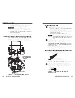
Page 12: ...nder board on the HSA 200CE or HSA 200SE Provide AC power 5 amps max for loop through to one additional HSA 200 unit Plug in a projector or other display device This outlet is a US style power outlet...

Page 13: ...der to adjust the top surface see Adjusting the Top Panel in chapter 3 with the top surface adjustment screw 8 8 Top surface adjustment screw After loosening the latch locking screws 7 adjust the top...

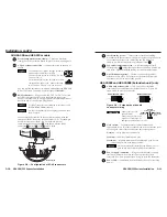
Page 14: ...pplying power with incorrect voltage polarity could damage the power supply and the Extender board in the HSA Captive Screw Terminal 12V Black Wire White Wire Figure 2 11 Power connector wiring Do not...

Page 15: ...and an input signal are present The LED lights amber when power is present but no input signal is present 5 RJ 45 connectors Plug a CAT 5 or CAT 6 twisted pair TP cable into each of these RJ 45 female...

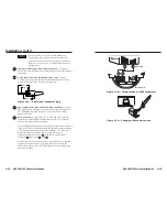
Page 16: ...be wired for an unbalanced stereo input signal and for the appropriate unbalanced or balanced output signal 3 If the input is from a laptop computer and no picture appears use a laptop breakout cable...

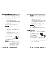
Page 17: ...y nicked or bent Exercise caution when handling and mounting the enclosure Mishandling may result in injury to the installer or damage the appearance of the enclosure The surfaces of the HSA enclosure...

Page 18: ...222 models only Disconnect both RJ 45 connectors from the underside of the enclosure by simultaneously performing steps 3a and 3b a With a Tweeker in one hand reach through the small access hole in th...

Page 19: ...sh the bezel through the front panel 7 Snap a replacement bezel in place If necessary replace the connector icon by prying the old icon off of the connector plug in with a Tweeker figure 3 4 and snapp...

Page 20: ...losure on a soft cloth 2 Loosen the three Phillips head screws that secure the gas lift mounting plate in place figure 3 5 Unscrew mounting plate from gas lift Loosen 3 screws Figure 3 5 Removing the...

Page 21: ...ve front access panel Figure 3 7 Front access panel removal HSA 222 models 8 Remove the pivot nut from the upper pivot bolt then remove the bolt releasing the upper end of the gas lift from the top pa...

Page 22: ...osened in step 2 Holding the plate in position with one hand secure it to the enclosure with the three screws 14 Reinstall the surface mount enclosure See Removing and Replacing the Enclosure steps 6...

Page 23: ...ations Maintenance and Modifications cont d HSA 200 222 Series Surface Access Products A Appendix A Reference Information Specifications HSA Part Numbers Included Parts Routing Templates Replacement P...

Page 24: ...2 0 V to 5 0 Vp p Output level TTL 5 0 Vp p unterminated Input impedance 510 ohms Output impedance 75 ohms Max propagation delay 18 8 ns Max rise fall time 4 ns Polarity Positive or negative follows i...

Page 25: ...Surface cutout inside rim 5 970 0 0325 W x 4 625 0 0325 D 15 16 0 083cmWx11 75 0 083cmD Top plate inside tilt plate 4 660 W x 2 875 D 11 84 cm W x 7 30 cm D HSA 200C HSA 200CE USA models Top plate out...

Page 26: ...nternational Safe Transit Association Listings certifications UL c UL Compliances HSA 200SE HSA 200CE CE FCC Class A VCCI AS NZS ICES MTBF 30 000 hours Warranty 3 years parts and labor All nominal lev...

Page 27: ...strations will help you properly prepare the mounting surface The surface cutout area is the shaded area on the diagrams The cutout dimensions are provided For full size paper templates visit the Extr...

Page 28: ...0 3 cm 8 5 21 6 cm SURFACE CUT OUT AREA 6 000 0 0325 15 24 0 083 cm diameter SURFACE CUT OUT AREA 8 0 20 3 cm diameter HSA 200C HSA200CE HSA222C US Models HSA 200C HSA 200CE International Models Cut s...

Page 29: ...ble to damage caused by mishandling during shipment if they are improperly packaged If for any reason you need to return an HSA to Extron first contact Extron to obtain a return kit The return kit whi...

Page 30: ......

Reviews: