3.
For a
Dual Display
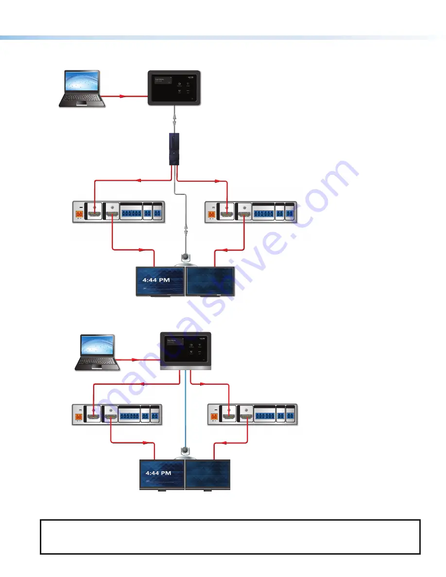
system, you need a second HD CTL 100. Connect HDMI cables from both of the MTR computer
HDMI
OUT
connectors to the
Input
connectors of the two HD CTL 100s (see figure 4 and figure 5).
POWER
12V
0.3A MAX
INPU
T
OUTPUT
+V OUT
DIGITAL I / O
HDMI/CEC
HDMI
G
24
IR / S
S G
2
1
G
4
3
G
HD CTL 100
HDMI
Display
Display
Laptop
HDMI/CEC
POWER
12V
0.3A MAX
INPU
T
OUTPUT
+V OUT
DIGITAL I / O
HDMI/CEC
HDMI
G
24
IR / S
S G
2
1
G
4
3
G
HDMI/CEC
HD CTL 100
HDMI
HDMI
USB
L
USB
Camera/
Mic/
Speaker
Touchscreen Control Panel
Di l
MODEL 80
FLAT PANEL
Microsoft
Teams
Rooms
Computer
Di l
D
MODEL 80
FLAT PANEL
Figure 4.
Cabling Diagram (Dual Display) for Touchscreen Control
POWER
12V
0.3A MAX
INPU
T
OUTPUT
+V OUT
DIGITAL I / O
HDMI/CEC
HDMI
G
24
IR / S
S G
2
1
G
4
3
G
HD CTL 100
HDMI
HDMI
Display
Display
Laptop
HDMI/CEC
POWER
12V
0.3A MAX
INPU
T
OUTPUT
+V OUT
DIGITAL I / O
HDMI/CEC
HDMI
G
24
IR / S
S G
2
1
G
4
3
G
HDMI
HDMI/CEC
HD CTL 100
USB
Camera/
Mic/
Speaker
All-in-one MTR Computer
L
Figure 5.
Cabling Diagram (Dual Display) for MTR Computer
NOTE:
on the previous page through figure 5 are controlled via CEC, which is accomplished using
the same HDMI cables for transporting video from the Microsoft Teams Rooms to the display. For instances where the
displays do not support CEC, use RS-232 or IR control. Enabling CEC on some displays may be required. Please consult
the display manual for instructions
4
5
3


