


2
HC 400 Series • Setup Guide (Continued)
POWER
12V
2.0
A MAX
INPUTS
OUTPUTS
1
TP
HDMI
L
R
AUDIO
HDMI/CEC
SIG
LINK
IN
COM
IR
DIGITAL I/O
1 2
S G
Tx Rx G
G 3 4 G
HCR 102
LAN
POWER
12V
3
0.5A MAX
2
RGB
HDMI
HDMI
AUDIO
4
INPUTS
HCT 103
CONTACT
TALLY
2 3 4 G 2 3 4 +V
REMOTE
SIG
LINK
OUT
Ethernet
PC with
GlobalViewer
Enterprise
ShareLink 200 N
AUDIO
OUT
LAN / PoE
VGA OUT
HDMI OUT
USB 3
POWER
5V
2.3A MAX
TCP/IP
Network
HCR 102
Scaling Receiver
Extron
Show Me Cables
Display
Extron
ShareLink 200 N
Collaboration
Gateway
HDMI
HDMI
RS-232
HDMI
VGA
Twisted Pair Cable (AV) 230'
HDMI
Ethernet
MODEL 80
FLAT PANEL
HCT 103
Switching Transmitter
Extron
OCS 100W
Wall Mount
Occupancy
Sensor
Wireless
Ethernet
Laptop
Room
Wireless Access
Point
Tablet
Smartphone
TCP/IP
Network
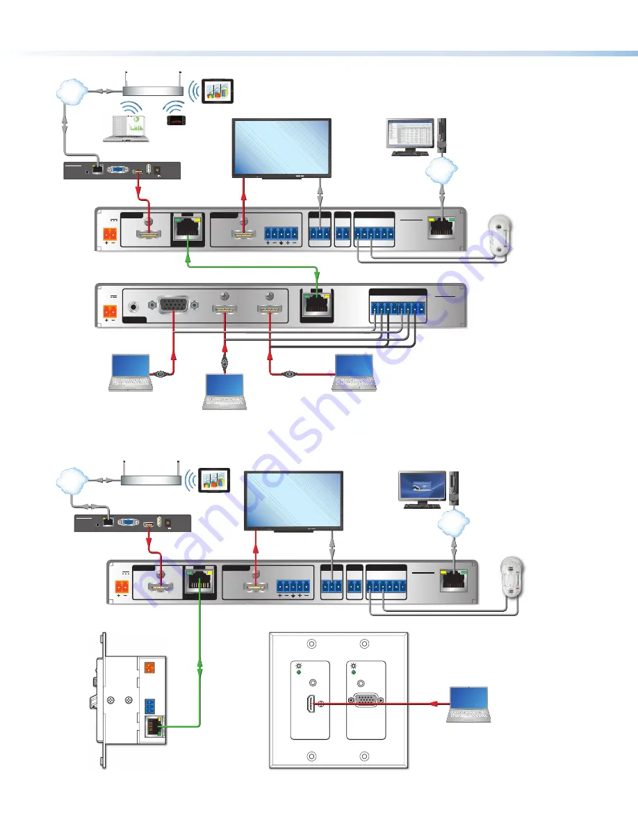
Figure 1.
A Typical TeamWork HC 404 System Application
POWER
12V
2.0
A MAX
INPUTS
OUTPUTS
1
TP
HDMI
L
R
AUDIO
HDMI/CEC
SIG
LINK
IN
COM
IR
DIGITAL I/O
1 2
S G
Tx Rx G
G 3 4 G
HCR 102
LAN
AUDIO IN
HDMI IN
AUDIO IN
VGA IN
Extron
Ethernet
PC with
GlobalViewer
Enterprise
ShareLink 200 N
AUDIO
OUT
LAN / PoE
VGA OUT
HDMI OUT
USB 3
POWER
5V
2.3A MAX
TCP/IP
Network
HCR 102
Scaling Receiver
Display
Extron
ShareLink 200 N
Collaboration
Gateway
HDMI
HDMI
RS-232
Twisted Pair
Cable (AV)
230'
HDMI
Ethernet
MODEL 80
FLAT PANEL
HCT 102 D
Switching Transmitter (Front)
HCT 102 D
Switching Transmitter (Side)
Extron
OCS 100W
Wall Mount
Occupancy
Sensor
Ethernet
Room
Wireless Access
Point
Tablet
TCP/IP
Network
Figure 2.
An HC 403 System Application
Panels and Features
Front Panel Features
CONFIG
HCR 102
1
INPUT
LPCM-2CH
MULTI-CH
HDCP
SIGNAL
R
MENU
ENTER
HOLD FOR 720p/1080p
1
HCT 103
2
3
4
INPUTS
HDCP
SIGNAL
2
3
4
AUDIO
HCR 102
A
I J
B
C
D
H
FG
E
HCT 103
B
C
D
Figure 3.
HCT 103 Front Panel (Top)
HCR 102 Front Panel (Middle),
HCT 102 D Front Panel Without Wallplate
(Bottom, Right)
A
Configuration
(Config) connector (USB mini-B), page 13
B
Input selection buttons
and
LEDs
, page 16
C
Input signal presence (Signal) LEDs
, page 16
D
HDCP status LEDs
, page 16
E
Audio input type LEDs
(LPCM-2Ch and Multi-Ch, page 16
F
Menu
button,
G
Enter
button, and
H
Navigation (
right
,
left
,
up
, and
down
arrow)
buttons (see
To configure the AV settings using the OSD
and front panel buttons:
on page 9)
I
Power LED (HCT 102 D), power and reset indicator LED
(HCR 102) (see below)
J
Reset button
(HCR 102) (see below and page 17)
K
Auto Switch LED (see below)
L
Service connector (for use by Extron support staff)
J
Reset button
(HCR 102) — Pressing this recessed button causes various product settings to be reset to the factory defaults
(see
Reset Modes: a Brief Summary
on page 17).
I
Reset and power LED
— This green LED indicates either the power status of the HCT 102 D transmitter or the HCR 102
receiver, or the reset mode of the receiver. LED indications are as follows:
HCT 102 D Transmitter
HCR 102 Receiver
•
Off
— The unit is not powered on.
•
On, lit amber
— The unit is powered on
but there is no active signal at that input.
•
On, lit green
— The unit is powered on
and there is an active signal at that input.
•
Off
— The unit is not powered on.
•
On, lit steadily
— The unit is powered on.
•
Blinking
— The unit is powering up or the HCR 102 is performing a
reset. The blink pattern depends on the selected reset mode.
For full descriptions of reset modes, how to use the reset button to activate
them, and details of LED indications of each mode, see the
HC 400 Series
User Guide
.
K
Auto Switch LED
— This LED on the HCT 102 D lights green if either of the auto-switching modes is enabled, and it turns off
if both of the auto-switch modes are disabled. For details on auto-switching modes, see the
HC 400 Series User Guide.
NOTE:
For AV connectors on the HCT 102 D, see
Rear and Side Panel Features
on page 4.


