


2
FOX3 SR 201 • Setup Guide (Continued)
b.
For remote control of a unit and loading firmware (LAN or USB only), connect a host device, such as a computer or control
system, to one of the following ports (see the
FOX3 SR 201 User Guide
, available at
www.extron.com
, for details):
•
Remote RS-232 port
— Connect the 3-pole captive screw connector to this port (
). The protocol for the Remote port
is as follows:
•
9600 baud
•
no parity
•
8 data bits
•
1 stop bit
•
no flow control
•
LAN Ethernet port
— Connect an RJ-45 connector to this port (
).
•
USB Configuration port
— Connect a USB mini-B connector to this port (see
Step 4 — Throughput Connections
NOTE:
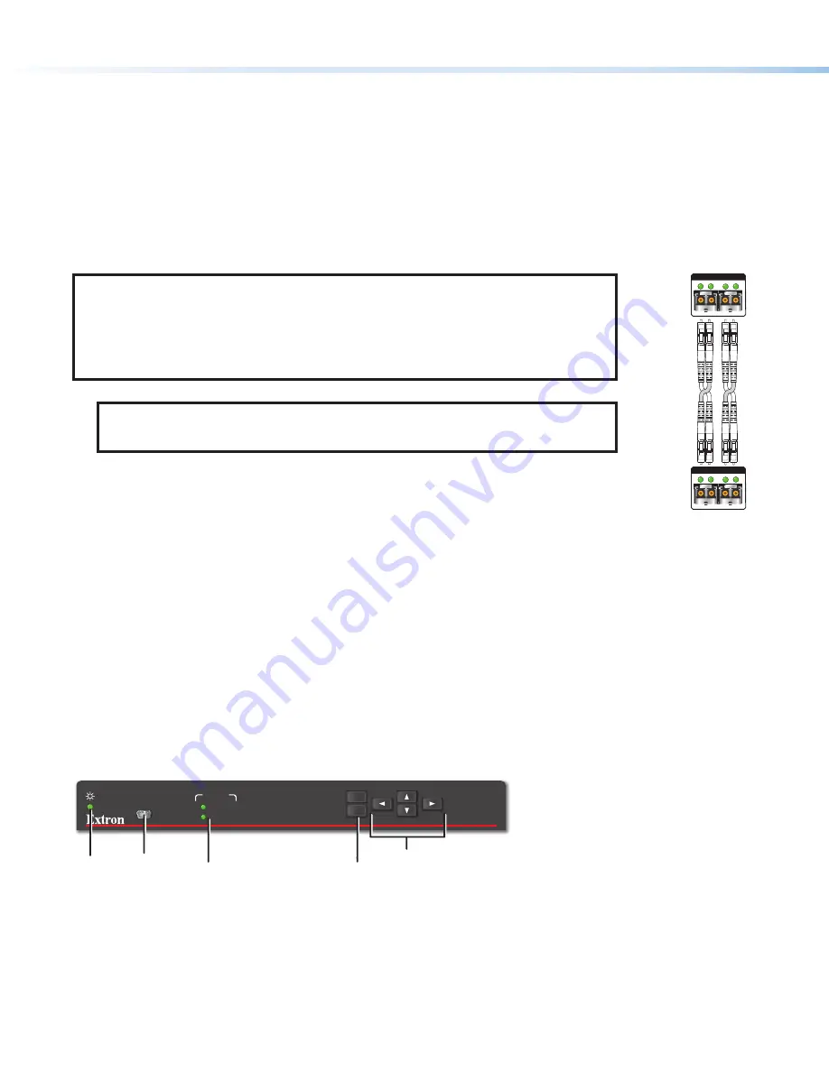
figure 4 for fiber cable connections. Connect the transmitter to a receiver in one of
three ways:
•
One way (transmitter to receiver) only, perform step 4a.
•
Two way (transmitter to receiver and return), perform steps 4a and 4b.
•
Output B is available to transmit 4K @ 60 Hz uncompressed signal when the FOX3
Uncompressed Video LinkLicense is purchased.
a.
Connect the fiber between the A Out port on the transmitter and the A In port on the receiver (
1
).
NOTE:
Ensure that the transmitter and connected receiver are in the same transmission
mode, singlemode (SM) or multimode (MM) and use the correct SM or MM fiber cable to
connect the devices.
b.
To return serial data from the receiver (such as responses from a controlled device) or IR data
to the transmitter, connect a cable between the A Out port on the receiver and A In port on the
transmitter (
2
).
c.
To transmit an uncompressed 4K @ 60 Hz signal, using the Uncompressed Video LinkLicense,
repeat step 4a on the SFP B port on the scaling receiver
SFP Link LEDs
—
Receiver
Transmitter
1
1
2
2
2
2
1
1
A
OUT IN
OUTPUTS
B
OUT IN
A
OUT IN
INPUTS
B
OUT IN
Figure 4.
Fiber Cable Connection
•
Transmit Optical OUT LED
— Lights solid green when powered and lights off when there is no power on the endpoint.
•
Receive Optical IN LED
— Lights solid green when light is present and lights off when there is no power or light present.
Step 5 — Power Connection
Connect the included external 12 VDC power supply into the 2-pole connector (see
lights (
) when the unit is receiving power.
Operation
After the receiver, transmitter, and their connected devices are powered up, the system is fully operational. If any problems are
encountered, verify that the cables are routed and connected properly and the display device has a compatible resolution and
refresh rate. If problems persist, call the Extron S3 Sales & Technical Support Hotline (see the
FOX3 SR 201
MENU
CONFIG
INPUT
SIGNAL
HDCP
ENTER
C
C
C
A
A
A
D
D
D
E
E
E
B
B
B
Figure 5.
FOX3 SR 201 Front Panel
A
Power LED
— Indicates power is applied to the unit.
B
USB Config port
— Connect a USB Mini-B cable to a computer to configure the device and update the firmware via Product
Configuration Software (PCS), Simple Instruction Set (SIS) commands, or internal web pages.
C
Input LEDs
—
•
Signal LED
— Lights when the unit detects an input video signal.
•
HDCP LED
— Lights when the input signal is HDCP encrypted.
step 4b
4
5


