1
Product Category
IMPOR
TANT
:
Go to
www
.extron.com
for th
e
complete user guide and installation
instructions befor
e connecting the
product to the power sou
rce.
EBP 1200C Cable Cubby Enclosure
with eBUS
®
Button Panel • Setup Guide
The Extron EBP 1200C is a Cable Cubby
®
1200 with an
integrated eBUS button panel to combine convenient
AV and data connectivity with a fully customizable AV
system control interface for use with Extron IPCP Pro
Series Control Processors.
NOTE:
These products are only for use with Extron
UL Listed IPCP Pro control processors.
This guide provides basic instructions for an
experienced installer to install an EBP 1200C Cable
Cubby button panel:
•
Setup Checklist
•
Installing the EBP 1200C Cable Cubby
•
Connecting to the eBUS System
For more details on eBUS, see the
eBUS Technology
Reference Guide
, available on
www.extron.com
. For
details on configuration, see the software help files.
HDMI
HDMI
3
HDMI
4
2
1 CONFIGURABLE
100-240V ~ --A MAX
50-60 Hz
AUDIO
OUTPUT
TALLY OUT
CONTACT IN
L
1
2
R
L
R
Tx Rx G
3
2
1
4 +V
1 2 3 4 G
RS-232
OUT
IN
HDMI
INPUT
REMOTE
POWER
12V
--A MAX
G
Tx Rx
RTS CTS
COM 1
G
Tx Rx
COM 2
V C G
VOL
RELAYS
1 2 C
1 2 3 4 G
DIGITAL I/O
PWR OUT = 6W
eBUS
+V +S -S G
LAN
IPCP PRO 250
IR/S
S G
Display with Speakers
Ethernet
TCP/IP
Network
Extron
IN1604 HD
Four Input Scaler
Extron
IPCP Pro 250
IP Link Pro
Control Processor
Extron
EBP 1200C
Cable Cubby eBUS
Button Panel
Laptop
Laptop
OFF
ON
LAPTOP
PC
MUTE
VGA
HDMI
AUX VIDEO
Extron
HDMI
eBUS
HDMI
HDMI
Computer
MODEL 80
FLAT PANEL
Ethernet
RS-232
VGA
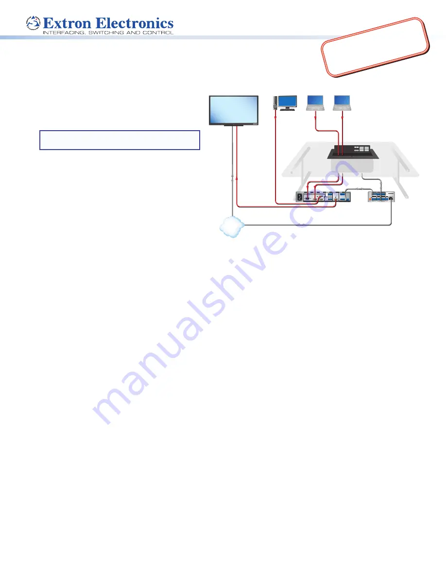
Figure 1.
EBP 1200C Application Diagram
Setup Checklist
Step 1 — Planning
Download and install the latest version of the software, firmware, and device drivers needed to configure the IPCP Pro
and control the connected AV products. See the
IPCP Pro Series User Guide
(available at
www.extron.com
) for details on
software and drivers.
Obtain network information (IP addresses, passwords, DHCP settings, and the like) and the MAC address for the control
processor.
Obtain model names, drivers, and setup information for AV devices.
Determine which eBUS cabling topologies to use and obtain cables, mounting hardware, and any power supplies or hubs
required by that configuration.
Make sure you are familiar with all the
Included parts
(see the next page) and have all the necessary tools for installing the
Cable Cubby.
Before cutting a hole in any furniture, select the best location for the EBP 1200C.
•
Ensure that the product is oriented so that the lid opens in the desired direction.
•
Ensure there is enough space for all the system cables and components, including cable retractors, if they are to be
installed.
Check all relevant regulations
(see the next page).
Step 2 — Cutting the Table
Decide on the method for cutting a hole in the table (see
Cutting the Table
on page 3).
Verify that you have the correct cut-out template and dimensions (see
Cutting the Table
on page 3).
Step 3 — Setting the eBUS ID Address
All eBUS devices connected to the same control processor must have a unique eBUS ID address. This requires access to the
DIP switches on the bottom panel of the EBP 1200C and it is more convenient to set the address before the EBP 1200C is
installed in the table (see
Setting the eBUS ID Address
on page 10).
www
.extro
n.com


