DTP2 T 201 D Transmitter • Installation and Operation
13
Operation
HDMI IN
LINK
a
DTP2 T 201 D
Front Panel
A
B
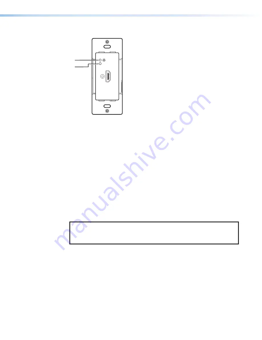
Figure 10.
DTP2 T 201 D Transmitter Power Indicator
Transmitter Power and Link Indicators
A
Power LED — This two-color front panel LED lights to indicate signal and power status
•
Amber — The unit is receiving power but no signal on the HDMI input.
•
Green — The unit is receiving power and a signal is present on the HDMI input.
B
LINK LED — This green LED lights to indicate when a valid link is established between
the units on the DTP cable.
System Operation
After the transmitter, compatible receiver, and their connected devices are powered up,
the system is fully operational. If any problems are encountered, ensure that all cables are
routed and connected properly.
NOTE
:
Ensure that the video source and display are properly connected to the system,
and that the transmitter, compatible receiver, and the display have power applied
before power is applied to the video source. If all other devices are not turned on
before the video source, the image may not appear.
Connecting to the Bottom Panel USB Port
Use the mini Type B USB port on the bottom panel (see
on the next page) to
connect the transmitter to a host computer to configure the unit with SIS commands or to
upload a newer version of firmware.
1.
Connect a USB A to mini B cable between the transmitter USB Config port and a
USB port of the PC.
10
Summary of Contents for DTP2 T 201 D
Page 2: ...Safety Instructions ...
Page 6: ......


