BBG 6 A • Installation
Installation
BBG 6 A • Connections, Indicators, and Controls
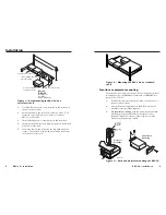
4
.
For furniture mounting
, drill 3/32" (2 mm) diameter pilot
holes, 1/4" (6.3 mm) deep in the mounting surface at the
marked screw locations.
5
.
For furniture mounting
, insert #8 wood screws into the
four pilot holes. Tighten each screw into the mounting
surface until just less than 1/4" (6.3 mm) of the screw head
protrudes.
6
.
For furniture mounting
, align the mounting screws with
the slots in the brackets and place the unit against the
surface, with the screws through the bracket slots.
7
.
For furniture mounting
, slide the unit slightly forward
or back, then tighten all four screws to secure the unit in
place.
8
.
For projector mounting
, secure the unit to a projector
mount or other surface by inserting the mounting bolt
through the bracket’s slotted hole.
Connections, Indicators, and Controls
See figure 4 below.
a
Power/Signal indicator LED
— When illuminated, this LED
indicates that the BBG 6 A is receiving power.
b
Blackburst only outputs — Connect up to four display devices
to these BNC connectors for blackburst output.
c
Blackburst/color bars outputs — Connect up to two display
devices to these BNC connectors for blackburst or color bars
output.
POWER
12V
.2A MAX
L
R
4
3
2
1
6
5
PA
L
NTSC
BLA
CKBURST
BLACKBURST
COLORBARS
-10
+4
1 2 3
ON
1 KHZ
AUDIO
BBG 6 A
BLACKBURST AND AUDIO
GENERATOR
1
2
6
3
4
7
5
Figure 4 — BBG 6 A front and rear panels
d
DIP switch — Use these DIP switches to select b4 dBu
(pro) or -10 dBV (consumer) audio output level, between NTSC
or PAL (USA only) output, and between blackburst or color bars
for outputs 1 and 2.
N
With the first DIP switch set to “+4,” the unit outputs
+4 dBu audio level with
balanced wiring. With the DIP
switch set to “-10,” the unit outputs -10 dBV audio level
with
unbalanced wiring.
NTSC
Blackburst
1 2 3
ON
Color bars
PAL
+4
-10
BBG 6 A
RESERVED
Blackburst
1 2 3
ON
Color bars
+4
-10
BBG 6 A J
Figure 5 — BBG 6 A and BBG 6 A J DIP switches
N
DIP switch 2 of the BBG A J is not used.
N
Please refer to the table below for other combinations.
Output
Dip
Switch
Position
Balanced Unbalanced
+4
-10
-4 dBV
+4 dBu
-2 dBu
-10 dBV
Summary of Contents for BBG 6 A J
Page 3: ......


