background image

Version 2.1 7/09 

11 

PC Software 

The supplied software combines 

data acquisition

 and 

datalogger

 functionality. 

In the Datalogger mode, the meter stores readings remotely (explained in previous section) 
then, at a later time, the meter is connected to the PC and the readings are transferred 
(addressed in this section). 
In the Data Acquisition mode, the meter takes readings while connected to the PC. The 
readings are taken, displayed, and stored all at the same time. 

PC Requirements


  486-33 IBM compatible PC or better 

 CD-ROM 

drive 

  Available serial port 

  Windows 95, 98, 2000, NT, ME, or XP Operating System 

Installing the Windows Application Program 

1.  Connect the BT100 to the serial PC port (COM1 or COM2) using the 9-pin female 

connector to the 9-pin male serial PC port cable supplied. 

2.  Place the supplied software CD in the PC CD-ROM drive 
3.  Wait for “Autorun” to start and follow the on-screen instructions 
4.  If “Autorun” does not start, click on “Start” then “Run”. Type the drive letter of the CD-

ROM and :\VB\Disk1\Setup.exe and click OK (To install the LabVIEW version, type the 
drive letter and :\LV\installer\Setup.exe and click OK). 

5.  Change the path if necessary or choose to install the program to its default location. 
6.  Launch the program by double clicking the program file in the location where it was 

saved during installation. 

7.  Do not run the supplied software until the meter is properly connected to the PC. 

Software Operation 

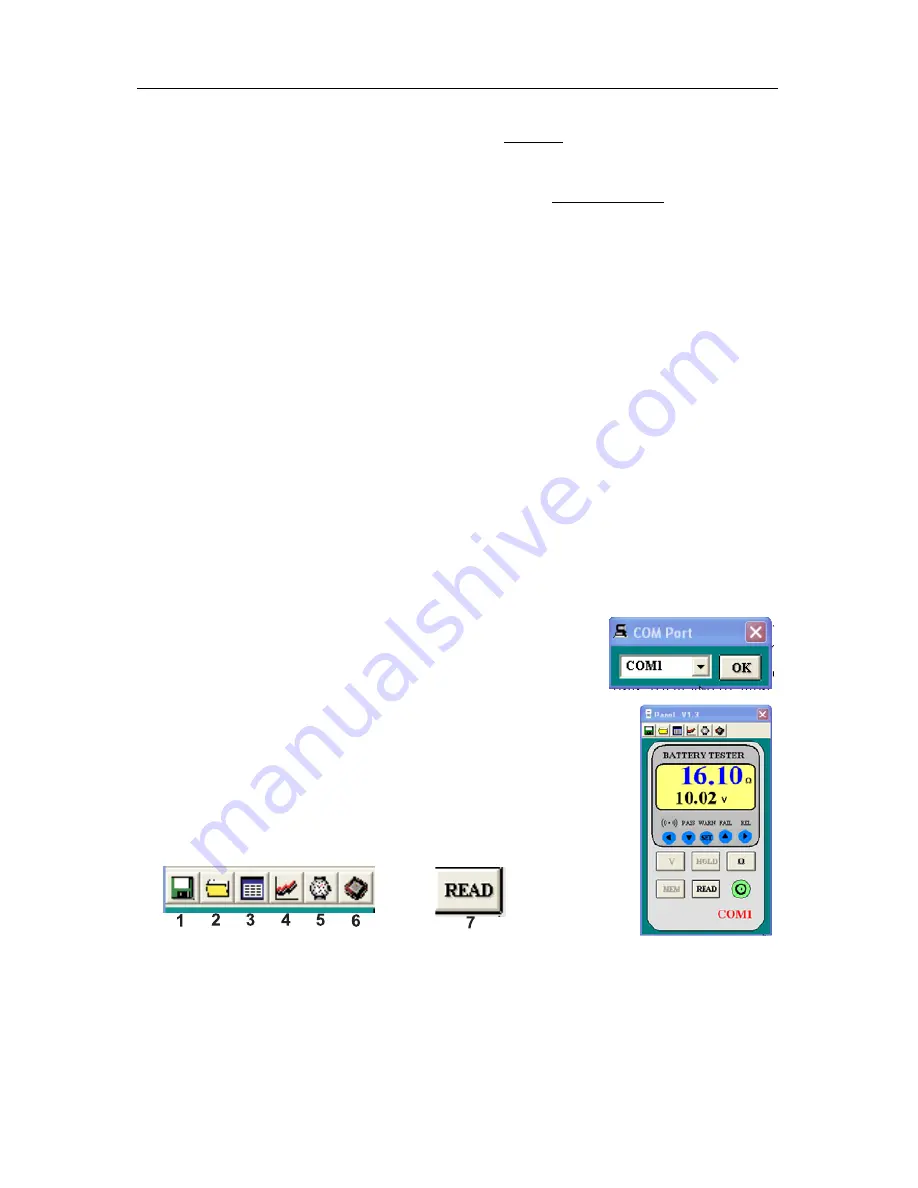
Click “Start” on the Start menu, click “Programs” and then click on 
“BatTester” to launch the program. The COM Port screen will 
appear. Select COM1 or COM2 then click OK 


The Battery Tester main screen will appear. On the lower right of the 
screen, “COM1” or “COM2” will appear if a connection has been 
accomplished. “NO COM” will appear if there is no connection. 
 
 
The function of the Main screen icons are: 


1. 

Opens the “Save As” dialog box to save data to a new file. 

2. 

Opens the “Open” dialog box to open a saved file. 

3. 

Opens the “Real Time List” display box for data acquisition mode. 

4. 

Opens the “Real Time Graph” of the voltage and resistance for data. 

5. 

Opens the “Real Time Sampling Rate” dialog box 

6. 

Opens the “Data Logger” box and downloads the data. 

7. 

Opens the “Manual Records” box and downloads the data. 

Summary of Contents for BT100

Page 1: ...User s Guide Battery Capacity Tester Model BT100 ...

Page 2: ...to be free of defects in parts and workmanship for one year from date of shipment a six month limited warranty applies on sensors and cables If it should become necessary to return the instrument for service during or beyond the warranty period contact the Customer Service Department at 781 890 7440 EXTENSION 210 for authorization or visit www extech com for more information A Return Authorization...

Page 3: ...stance High and Low limits and voltage threshhold point Number of comparator settings 99 sets Comparator output LEDs for pass green warning yellow and fail red results audible tone for warning and fail Resistance Voltage Lo IN Hi Lo Warning Warning Fail Hi PASS Warning Fail Manual Data logging 999 sets Continuous Data logging 9600 sets Operating environment 32 to 104 F 0 to 40 C 80 RH non condensi...

Page 4: ...ge Resolution Measurement current Accuracy 40mΩ 10µΩ 37 5mA approx 400mΩ 100µΩ 3 75mA approx 4Ω 1mΩ 375µA approx 40Ω 10mΩ 37 5µA approx 1 reading 10digits Voltage Measurement Temperature coefficient 0 1 rdg 0 5digits C Range Resolution Accuracy 4V 1mV 40V 10mV 0 1 reading 6digits Maximum Input Voltage 50VDC maximum No AC voltage input 60VDC and AC maximum between input terminals and ground DANGER ...

Page 5: ...al time setting mode for continuous data logging 6 Ω RANGE button Select the resistance range 40mΩ 400mΩ 4Ω 40Ω 7 REL button Press button to move the cursor to the right Press REL Relative button to zero the reading 8 button Press button to increase the displayed value 9 SET button Press SET button to switch the comparator mode on or off Press and hold the SET button for 2 seconds to enter the com...

Page 6: ...ual datalogging enabled M Continuous datalogging enabled Flashes when data is stored INTV Interval time settings of continuous datalogging function 1 255 seconds COMP SET Comparator settings HIGH High limit setting of the comparator resistance voltage LOW Low limit setting of the comparator resistance LED Display Indicators PASS green LED Battery complies with the high limit of comparator WARNING ...

Page 7: ... in injury or damage to the unit Do not attempt to measure the voltage of a generator This would result in an AC voltage being applied to the voltage generating output terminals which is dangerous After measuring a high voltage battery before continuing to measure a low voltage battery first short the measurement leads together This will discharge the DC elimination capacitor which is connected ac...

Page 8: ...asured DC voltage or battery internal resistance value is over range OL is displayed When the AC test current faults will be displayed REL Zero Adjust The REL function zeros the selected range of resistance and voltage The reading displayed when the REL button is pressed will be taken as zero and will be used to calibrate subsequent measurements 1 Short the 4 tips of red and black test leads probe...

Page 9: ... button one time the right two digits of the high limit resistance will be flashing Use the and buttons to select the desired value 8 Press button one time the left two digits of the threshold voltage will be flashing Use the and buttons to select the desired value 9 Press button one time the right two digits of the threshold voltage will be flashing Use the and buttons to select the desired value...

Page 10: ...t the desired interval time from 1 second to 255 seconds 3 Press SET button to exit interval time setting 4 Press M MEMORY button for 2 seconds to enter continuous logging mode the display will show M 5 The M will flash every time a reading is stored 6 Press M MEMORY button again to exit continuous logging mode 7 Data stored using continuous datalogging can not be read directly on the tester s dis...

Page 11: ...etup exe and click OK To install the LabVIEW version type the drive letter and LV installer Setup exe and click OK 5 Change the path if necessary or choose to install the program to its default location 6 Launch the program by double clicking the program file in the location where it was saved during installation 7 Do not run the supplied software until the meter is properly connected to the PC So...

Page 12: ...e displayed as a List a Voltage graph or a Resistance graph Sampling Rate Setting for Data Acquisition Mode The sampling rate for the data acquisition mode can be set from 1 reading per second to 1 reading every 86 400 seconds 1 sample every 24 hours Note This sampling rate setting is for the data acquisition mode only For datalogger mode the sample rate is set using the meter s front panel contro...

Page 13: ...Time box appears Enter the exact time and date of the first reading in the file The software will then put a time and date stamp on all of the records in the file The data will automatically download at this time The recalled data can be viewed as a list or graph and can be saved as file READ Button Data stored manually single press of the MEMORY button on the meter can be downloaded by clicking t...

Page 14: ...olvents on this instrument Battery Check Replacement 1 The symbol will be displayed when the batteries need replacement 2 a Disconnect the test leads b Turning off the tester c Open the battery cover with a screw driver d Replace the batteries e Replace and secure the battery cover Calibration and Repair Services Extech offers complete repair and calibration services for all of the products we sel...

Reviews: