WARNING
MEASUREMENT OF VOLTAGE IN OSCILLOSCOPE MODE
GREATER THAN 250VAC OR 360VDC
WILL RESULT IN PERMANENT DAMAGE AND POSSIBLE INJURY
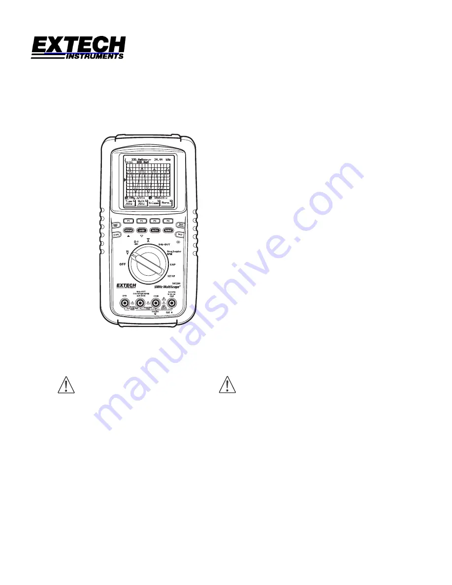
User's Guide Handheld MultiScope
Model 381285
查询"381285"供应商
Page 1: ...WARNING MEASUREMENT OF VOLTAGE IN OSCILLOSCOPE MODE GREATER THAN 250VAC OR 360VDC WILL RESULT IN PERMANENT DAMAGE AND POSSIBLE INJURY User s Guide Handheld MultiScope Model 381285 查询 381285 供应商 ...
Page 2: ...on 12 Cursor 13 Operation Digital Multimeter 14 AC and DC Volts 14 Resistance 15 Continuity 15 Diode 15 AC and DC Current 16 Capacitance 16 Relative 17 Avg Min Max 17 Peak Hold 17 Limit 18 Sig Out 18 Frequency Counter Duty Cycle and Dwell 19 Automotive RPM 19 Logic Analyzer 19 Set Up 20 Aux 20 Backlight 21 Auto Manual Range 21 Help 21 Print 21 Tilt Stand 21 RS232 Commuincations 22 Maintenance 23 B...
Page 3: ...tech The sender is responsible for shipping charges freight insurance and proper packaging to prevent damage in transit This warranty does not apply to defects resulting from action of the user such as misuse improper wiring operation outside of specification improper maintenance or repair or unauthorized modification Extech specifically disclaims any implied warranties or merchantability or fitne...
Page 4: ...hile the function switch is in the current resistance or diode mode Doing so can damage the meter 5 ALWAYS discharge capacitors in power supplies and disconnect the power when making resistance or diode tests 6 ALWAYS turn off the power and disconnect the test leads before opening the back to replace the fuse or batteries 7 NEVER operate the meter unless the back cover is in place and fastened sec...
Page 5: ...mV 1 0 rdg 10dgt 5 0 rdg 10dgt not specified 4V 1mV 2 0 rdg 10dgt 40V 10mV 400V 100mV 0 75 rdg 10dgt 1 0 rdg 10dgt 5 rdg 5dgt 700 V 1V 1 0 rdg 10dgt not specified not specified Resistance Ranges Resolution Accuracy 400Ω 0 1Ω 4kΩ 1Ω 40kΩ 10Ω 400kΩ 0 1kΩ 4MΩ 1MΩ 0 5 rdg 10dgt 40MΩ 10MΩ 1 rdg 5dgt DC Current Ranges Resolution Accuracy 40mA 0 01mA 400mA 0 1mA 1 2 rdg 10dgt 4A 1mA 20A 10mA 1 5 rdg 10dg...
Page 6: ...motive RPM Range RPM1 RPM2 0 to 12000 rpm DIS electronic type engine 2 cycle engine Distributor type engine 4 cycle engine Logic Analyzer Channels Sweep Time Sweep Mode 1 125ns to 2s per division 23 divisions Auto Diode Test Open circuit voltage 5V max dB 80 to 80dB 2 3 8 16 50 75 93 110 125 135 150 300 600 900 1000 or 1200 ohms reference Continuity Buzzer sounds for 60Ω Auxiliary Input 400 0mV DC...
Page 7: ...rest Factor 3 at full scale 5 at half scale Input Impedance 10MΩ for numerical display 1MΩ for graphical display Auto Power Off 30 minutes with disable feature Min Max Avg Displays minimum average maximum readings over time Hold Captures displayed reading Overrange Indicates OVER Storage 15 pages text or graphics Dimensions 3 6x7 6x2 2inches 92x192x55mm Weight 1 0lbs 450gm Power 6 size AA cells 6 ...
Page 8: ...waveform Hz hertz frequency MANU manual RESET reset MAX maximum MIN minimum ms milliseconds ºC degrees centigrade ºF degrees fahrenheit PAUSE pause in min max peakhold single glitch mode P H peak hold RANGE manual range REL relative RPM 1 2 stroke DIS Engine RPM 2 4 stroke Engine RUN restart in peak hold min max mode SAVE saves present signal in memory SINGLE single waveform SLEEP auto shut off TE...
Page 9: ... mode also power reset key to re activate power if the auto shutoff is in effect Save and recall measurement data or graphical display also press for 3 seconds to print data or the graphical display Display the basic meter warning Input jack locations and test procedures also press for 3 seconds to enable the RS232 interface Toggle between AUTORANGE and MANUAL RANGE Toggle between AC and DC measur...
Page 10: ... the probe tips are contacting the metal contacts inside the outlet before assuming that no voltage is present CAUTION Do not measure AC or DC voltages if a motor on the circuit is being switched ON or OFF Large voltage surges may occur during the ON or OFF operations that can damage the meter CAUTION To avoid meter damage do not apply 700V AC or 1000V DC for more than 10 seconds 1 Insert the blac...
Page 11: ...plitude in the autoranging mode or volts division can be set manually using F2 and the sub menu arrow keys The symbol indicates that autoranging has been selected F3 TRIGGER level EXIT F1 F2 F3 F4 The F1 slope key selects either a rising or falling trigger edge The F2 and F3 key adjust the trigger level The F3 EXIT key to return to the main screen F4 MORE function The MORE key redefines the functi...
Page 12: ...rigger a new measurement SEARCHING will appear on the display until a pulse arrives that triggers the event The F2 and F3 arrow keys adjust the time per division and trigger a new measurement The F4 EXIT key returns the screen to the More menu F3 POSITION RESET EXIT F1 F2 F3 F4 The POSITION key adjusts the vertical position of the waveform The F1 RESET key sets the vertical position cursor to the ...
Page 13: ...rrow keys to set the location of the cursors t F2 of one cycle Measures the time between the left and right cursor and displays it as a percentage of one cycle of the input waveform Select Left or Right and press the arrow keys to set the location of the cursors t F3 Time difference Measures the time difference between the left and right cursor For example the time difference cursor function can b...
Page 14: ...cting the metal contacts inside the outlet before assuming that no voltage is present CAUTION Do not measure AC or DC voltages if a motor on the circuit is being switched ON or OFF Large voltage surges may occur during the ON or OFF operations that can damage the meter CAUTION To avoid meter damage do not apply 700V AC or 1000V DC for more than 10 seconds 1 Insert the black test lead banana plug i...
Page 15: ... COM jack and the red test lead banana plug into the positive Ω jack 2 Set the function switch to the Ω position 3 Press the F2 key to select the Continuity function 4 Touch the test probe tips to the circuit or wire you wish to check If the resistance is less than 60Ω the audible signal will sound DIODE test WARNING To avoid electric shock do not test any diode that has voltage on it 1 Insert the...
Page 16: ...he mA or 20A function 5 Connect the test probe tips in series with the circuit under test The display will indicate the proper decimal point value and symbol CAPACITANCE WARNING To avoid electric shock disconnect power to the unit under test and discharge all capacitors before taking any capacitance measurements Remove the batteries and unplug the line cords 1 Insert the black test lead into the n...
Page 17: ... The display will indicate the maximum value the average value and the minimum value since the feature was initiated The meter will beep each time the MAX or MIN value is updated 3 The elapsed time for each value is displayed next to the value The time format is hrs min sec 4 Press F1 Restart to reset the time and begin recording a new series 5 Press F2 RUN PAUSE to run or pause the recording 6 Pr...
Page 18: ...value fall between the maximum and minimum limits the display will indicate PASS 7 If the measured value is greater than the maximum limit HIGH will be displayed and if the value is less than the minimum limit LOW will be displayed SIG OUT The Signal Out function generates a 5V pk pk square wave of 2 5Hz to 78kHz 1 Insert the test leads into the positive SIG OUT and the COM jacks 2 Set the functio...
Page 19: ... rpm 2 key for conventional 4 stroke distributor type engines 5 Read the rpm on the display NOTE To avoid interference from noise or outside sources keep the meter away from spark plugs or coil wires LOGIC ANALYZER WARNING To avoid meter damage never measure signals greater than 40V dc when in the Logic Analyzer function 1 Insert the black test lead into the negative COM jack and the red test lead...
Page 20: ...he auxiliary selection allows direct display of ºC ºF RH High DC Currents in the correct units when the meter is used with an external DC Adapter The external DC Adapter should output 1mV DC unit of measure 1 Insert the black adapter banana plug into the negative COM jack and red adapter banana plug in to the positive AUX jack 2 Set the function switch to the SET UP position 3 Press the F4 More ke...
Page 21: ... or graphical displays can be saved in memory 1 Press the SAVE key to enter this feature 2 The display will list 15 memory locations and indicates what type of data is stored in each location Locations with no data will be left blank 3 Press the CURSOR or LOGIC arrow keys to scroll the arrow cursor up down through the 15 memory locations 4 At the selected memory location a Press the F1 Save key to...
Page 22: ...etup dB to select the dB reference impedance c Select Setup Baudrate to select the communications baud rate 4 View Menu a Select View Bar to display the data as a bar plot b Select View Line to display the data as a line plot c Select View Text to display the data in a numeric format 5 Run Menu Select Star Stop or Pause to control the datalogging 6 File Menu a Select File Save to save the recorded...
Page 23: ...s are installed 1 Disconnect and remove the test leads 2 Remove the rubber holster if installed 3 Lift the Tilt Stand and remove the two screws using Philips screw driver 4 Lift the two battery covers up to remove them 5 Remove the Tilt Stand 6 Align the three batteries as shown in the diagram observe polarity and press down until they snap into the battery holder 7 Snap the two battery covers bac...
Page 24: ... 5 Remove the one screw at the rear bottom of the rear case and the two screws in the battery compartments 6 Lift the rear case far enough to gain access to the fuses located opposite the input terminals 7 Replace the blown fuse There are two fuses 250V 500mA for the 400mA range and 250V 20A for the 20A range 8 Replace the bottom case and secure with three screws Replace the battery covers and til...