Mounting and Adjusting the Finder Scope
To align the finder scope, perform steps 1 through 5 during the daytime; perform step 6 at night.
1. Slide the track on the bottom of the finder scope into the slot in the finder scope mounting assembly (
1, Fig.3
). To secure the
finder scope to the mounting assembly, tighten the two thumbscrews (
2, Fig. 3
)
to a firm feel only.
2. If you have not already done so, insert the 30mm 70° Series eyepiece into the eyepiece holder.
3. Point the telescope at some well-defined and stationary land object at least 200 m distant, such as the top of a telephone pole or
street sign. Center the object in the telescope eyepiece.
4. Look through the finder scope eyepiece and loosen or tighten, as appropriate, one or more of the finder scope collimation screws
(
2, Fig. 4
) until the finder scope crosshairs are precisely centered on the object you previously centered in the telescope eyepiece.
5. Check this alignment on a celestial object, such as the Moon or a bright star, and make any necessary refinements, using the
method outlined in steps 3 through 5.
NOTE: The two screws on the top of the finder scope (1, Fig. 4) are not adjustment screws. They are spring loaded used to
hold the finder scope
.
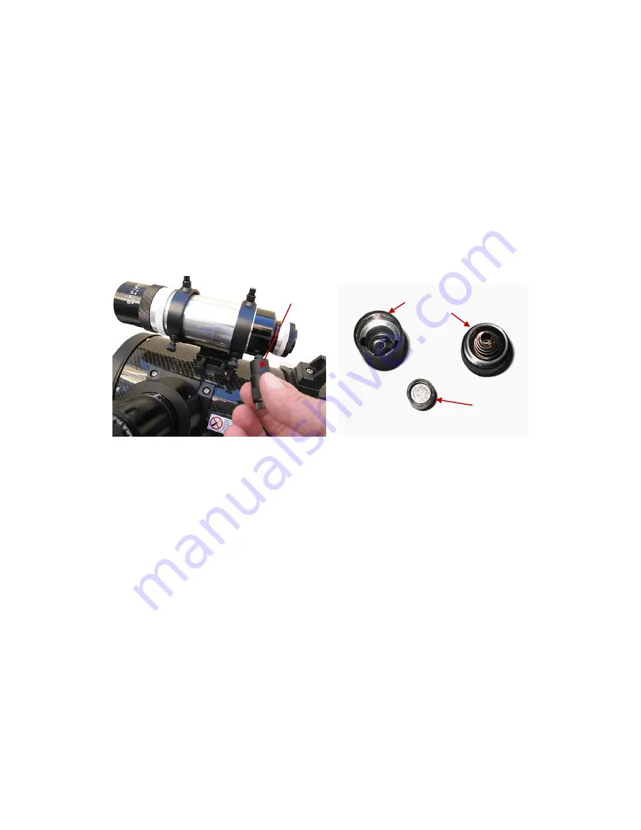
Using the Finder Scope Illuminator
The finder scope illuminator has a continuously adjustable brightness knob with click on and click off positions. To switch the
illuminator on, turn the adjustment knob clockwise (
1, Fig. 5
), past the click stop. The illuminator gets brighter as you turn it further
clockwise. For best results for astronomy use the illuminator at the dimmest setting that allows you to comfortably see the
crosshairs (which will glow red).
The batteries will last several hours of continuous illumination (less in cold weather, more in warm conditions). When not using the
finder scope, turn the illuminator off, by turning the knob counter-clockwise past the click stop.
To replace the batteries follow these steps:
1. Unthread the illuminator from the finder scope by grasping the entire unit and twisting it counterclockwise until it is free.
2. Separate the two halves of the illuminator by grasping the two ends (
1 and 2, Fig. 6
) and twisting counterclockwise.
Carefully separate the two halves when you feel that the illuminator pieces are free so that the batteries (and the blac k
plastic sleeve that hold batteries) don’t fall on the ground.
3. Tip the bottom half of the illuminator so that the batteries and the sleeve (
3, Fig. 6
) drop in your hand.
4. Push the two LR41 (1.5v) batteries out of the plastic sleeve and replace them with fresh batteries so that the positive ends
are in series (not facing each other).
5. Replace the batteries with the sleeve in the bottom half of the assembly so that the negative ends of the batteries are
facing the LED illuminator.
6. Replace the top half of the illuminator by turning the two halves clockwise until firm.
7. Test the illuminator by switching it on past the click stop.
8. If the illuminator tests okay, then attach the illuminator back on to the finder scope.
NOTE: If the illuminator does not turn on, recheck the battery position for the correct polarity position.
If the polarity is correct, test the batteries to make sure that they have a full charge.
If the battery polarity is correct and they have a full charge but still do not work, clean the battery
terminals by rubbing them with a pencil eraser and try again. If you have further trouble please contact Customer Service.
Fig. 5, Finder Scope Illuminator
Fig. 6, Illuminator and Batteries
1
1
2
3


