

109-3195 Rev. C
Page 7 of 9
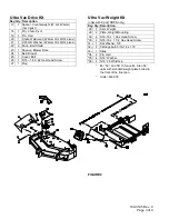
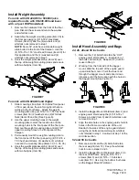
Install Weight Assembly
For units with SN 440,000 to 599,999 (also
required for units with SN 439,999 and lower
with a 2 post ROPS installed):
1. Remove the hardware from the front of the floor
pan. Discard the screws and retain the washer
and whizlock nuts.
2. Assemble the weight mounting plate (Item 29) to
the floor pan using (4) 5/16-18x1 Hex Head
Screws (Item 30) and the (4) washers and (4)
whizlock nuts removed in step 1.
NOTE
: Some 52” units have a standard weight
plate bolted to the front of the floorpan. Use the
(4) 5/16-18 x 1.50” Hex Head Screws (Item 30) for
this application and the (4) washers and (4)
whizlock nuts removed in step 1.
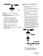
3. Hook the weight plate assembly (Item 28) over
the top of the weight mounting plates and secure
with two hairpins (Item 34).
FIGURE 7
For units with SN 600,000 and Higher:
1. Slide mounting strap (Item 33) behind front panel
of floor pan, above the reinforcing bars that are
welded to the front frame. Attach the weight
mounting plate using (2) 5/16-18 x 1.50 hex head
screws (Item 30) (2) washers and (2) Whizlock
Nuts (Items 35 and 36) (See Figure 8).
2. Use the upper mounting holes of the weight
mounting plate to mark the location to drill the
mounting holes in the front panel of the floor pan.
Remove the weight mounting plate and drill 3/8”
upper mounting holes in the front panel of the
floorpan.
3. Permanently mount the weight mounting plate to
the front panel of the floor pan using (4) 5/16-18 x
1.50 hex head screws, (4) washers, (4) whizlock
nuts and the mounting strap (Items 30, 33, 35, 36)
4. Hook the weight plate assembly (Item 28) over
the top of the weight mounting plates and secure
with two hairpins (Item 34).
FIGURE 8
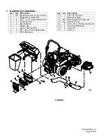
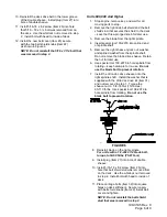
Install Hood Assembly and Bags
44, 46, 48 and 50 inch units
1. Remove the (12) bolts that retain the “HOT”
engine guard shield (Item 1). Discard (8) of
the bolts and retain (4). Keep all (12) nuts for
reuse in Step 3.
2. Working from the front side of the bagger
mount, slide the top end of the engine guard
up and into the mount. Pivot the lower end
through the bagger mount and slide it down
into place until the holes align with the holes in
the bagger mount (See Figure 9).
FIGURE 9
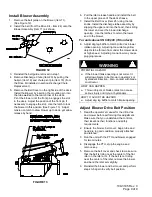
3. Install the Bagger Mount Weldment (Item 2) and
engine guard shield using the (8) 5/16-18 x 1
Screws provided (Item 3) and (8) whizlock nuts
removed in step 1.
4. Align the side holes in the engine guard shield to
holes in the frame on each side of the unit.
Reattach the sides of the engine guard shield
using the (4) bolts and remaining (4) whizlock
nuts retained in step 1. Continue at step 1 of the
All Units
section.
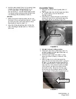
52 and 56 inch units
1. Remove and discard the (8) bolts that retain
the rear weight (Item 12). Keep the whizlock
nuts for use in steps 2 and 3.
2. Install the Bagger Mount Weldment (Item 2) to
the rear of the frame using (4) 5/16-18 x 1
screws (Item 3) and (4) 5/16 – 18 whizlock
nuts (Item 15). Use only the bottom four holes
on the Bagger Mount Weldment


