Maintenance
g011735
Figure 30
1.
Feeler gauge
•
If the gap is less than 0.010 inch, then
reinstall the shim and reference the
Troubleshooting
section.
•
If the gap is sufficient, proceed to the
safety check in step F.
F.
Perform the following safety check:
a.
Start the engine.
b.
Make sure the blades Do Not engage with
the PTO switch “off ” and the clutch
disengaged.
If the clutch does not disengage,
reinstall the shim and reference the
Troubleshooting
section.
c.
Engage and disengage the PTO switch
ten consecutive times to ensure the clutch
is functioning properly. If the clutch
does not engage properly, reference the
Troubleshooting
section.
Motion Control Adjustment
Located in the front inside the tower. Rotating the
pump linkage with a 9/16 inch wrench allows fine
tuning adjustments so that the machine does not
move in neutral. Any adjustments should be made
for neutral positioning only.
1.
Prior to starting the engine, pull the deck lift
handle rearward and push the button down, on
the top of the lever, to unlatch from transport.
Lower deck to the ground.
2.
Raise the rear of machine up and support with
jack stands (or equivalent support) just high
enough to allow drive wheels to turn freely.
3.
Start engine. Brake must be engaged and motion
control levers out to start engine. Run engine at
full throttle and release brake.
4.
Run the unit at least 5 minutes with the drive
levers at full forward speed to bring hydraulic oil
up to operating temperature.
Note:
The motion control lever needs to be in
neutral while making any necessary adjustments.
5.
Bring the motion control levers into the neutral
position. Access the links from the front of the
tower (Figure 31). Adjust pump control rod
lengths by loosening the bottom nuts on each and
rotating the turn buckle until the wheels slightly
creep in reverse (Figure 31). Pumps have a return
to neutral arms and will return to neutral when
the control levers are released. If the levers do not
fold out, adjust the links until the lever folds out
in the middle of the neutral lock notch. Move the
levers to the full forward and reverse. If the levers
fold out, tighten the jam nuts on the links.
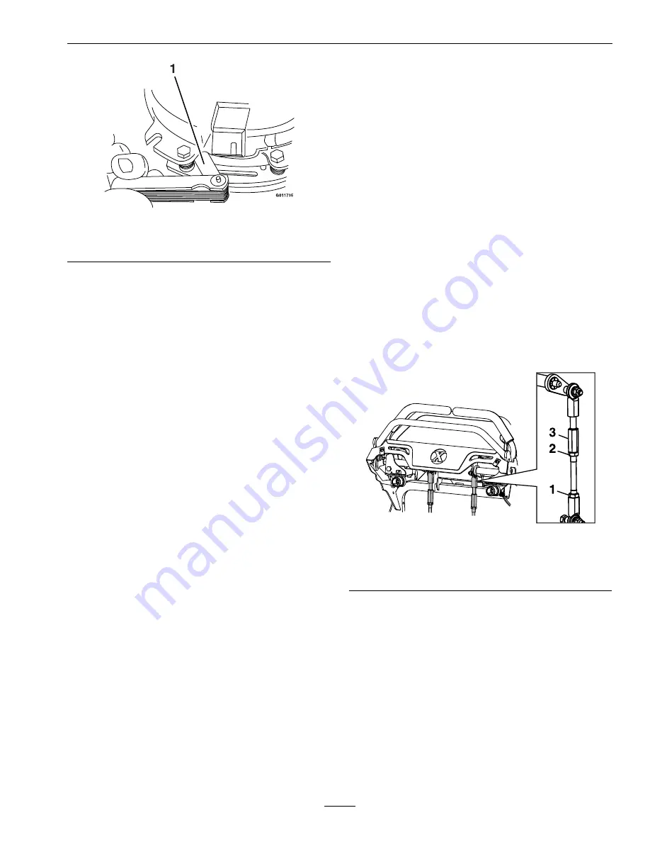
g267312
Figure 31
1.
Lower nut
3.
Links
2.
Upper nut
6.
Shut off unit.
7.
Remove the jack stands.
8.
Raise the deck and re-install the height of cut pin.
9.
Check that the machine does not creep in neutral
with the park brakes disengaged.
Adjust Motion Control
Handle Position
If the motion control levers do not align horizontally,
adjust one or both levers.
43
Summary of Contents for STARIS S Series
Page 1: ...STARIS S SERIES For Serial Nos 408 644 346 Higher Part No 4505 317 Rev A ...
Page 50: ...Schematics Schematics Electrical Schematic Kawasaki g303795 50 ...
Page 51: ...Schematics Electrical Schematic Kohler EFI g303794 51 ...
Page 52: ...Schematics Hydraulic Diagram g304191 52 ...
Page 54: ...Service Record Date Description of Work Done Service Done By 54 ...
Page 55: ...55 ...


