background image

Maintenance

3. Remove the foam sleeve from the element.

4. Gently tap the pleated side of the paper element

to dislodge dirt. Do Not wash the paper element
or use pressurized air, as this will damage the
element. Replace a dirty, bent, or damaged
element. Handle new elements carefully; Do Not
use if the rubber seal or foam sleeve is damaged.

5. Wash the foam sleeve in warm water and allow to

dry. Reinstall over the paper element.

6. Clean all air cleaner components of any

accumulated dirt or foreign material. Prevent any
dirt from entering the carburetor.

7. Install the air cleaner element with the pleated

side “out” and seat the rubber seal onto the edges
of the air cleaner base.

8. Reinstall the air cleaner cover and secure with

the knobs.

Servicing the Engine Oil

Checking the Oil Level

Service Interval: Before each use or daily

1. Park the machine on a level surface, disengage

the blade control switch, stop the engine, engage
parking brake, and remove the key.

2. Make sure the engine is stopped, level, and is cool

so the oil has had time to drain into the sump.

3. To keep dirt, grass clippings, etc., out of

the engine, clean the area around the oil fill
cap/dipstick before removing it.

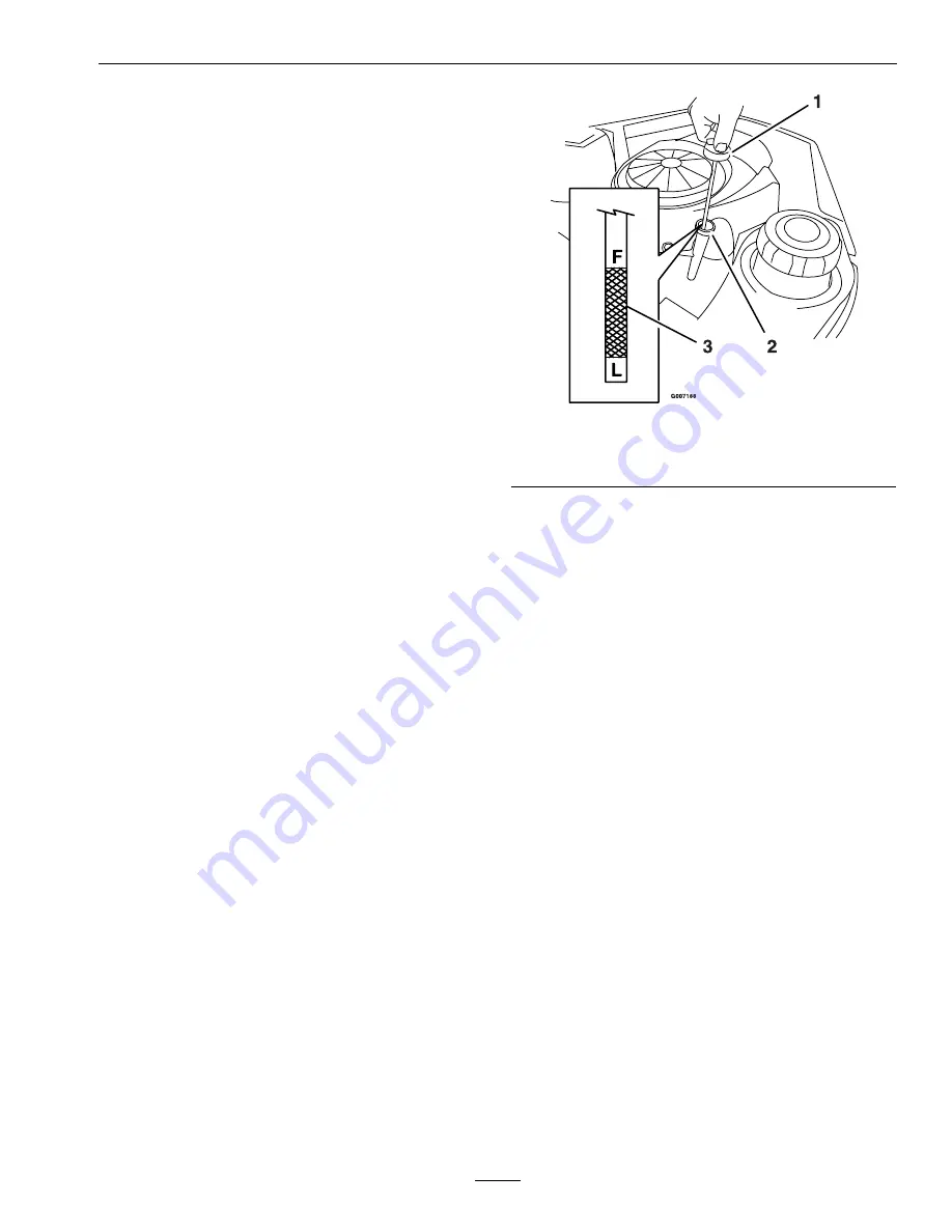
4. Pull and remove the oil fill cap/dipstick; wipe oil

off. Reinsert the dipstick and push firmly into
place (Figure 20).

Figure 20

1.

Oil dipstick

3.

Oil level

2.

Filler tube

5. Remove the dipstick and check the oil level.

The oil level should be up to, but not over, the
“F” mark on the dipstick.

6. If the level is low, add oil of the proper type, up to

the “F” mark on the dipstick. Always check the
level with the dipstick before adding more oil.

Note:

To prevent extensive engine wear or

damage, always maintain the proper oil level in
the crankcase. Never operate the engine with the
oil level below the “L” mark or over the “F” mark
on the dipstick.

Changing the Oil and Filter

Service Interval: After the first 5 hours

Every 100 hours/Yearly
(whichever comes first)
thereafter.

Change the oil and filter while the engine is still
warm. The oil will flow more freely and carry away
more impurities. Make sure the engine is level when
filling, checking, or changing the oil.

1. Start the engine and let it run until warm. This

warms the oil so it drains better.

2. Disengage the blade control switch and move the

motion controls outward to the neutral position
and engage parking brake.

31

Summary of Contents for Quest 4500-450

Page 1: ...QUEST For Serial Nos 790 000 Higher Part No 4500 450 Rev A ...

Page 2: ...SO 14982 EN 55012 The enclosed Engine Owner s Manual is supplied for information regarding the US Environmental Protection Agency EPA and the California Emission Control Regulation of emission systems maintenance and warranty Replacements may be ordered through the engine manufacturer For models with stated engine horsepower the gross horsepower of the engine was laboratory rated by the engine man...

Page 3: ...for product and accessory information or help finding a dealer Whenever you need service genuine Exmark parts or additional information contact an Authorized Service Dealer or Exmark Customer Service and have the model and serial numbers of your product ready Figure 1 identifies the location of the model and serial numbers on the product Write the numbers in the space provided Figure 1 Behind the ...

Page 4: ...rge 25 Transporting 25 Operating Tips 26 Maintenance 28 Recommended Maintenance Schedule s 28 Premaintenance Procedures 29 Raising the Seat 29 Accessing the Battery 29 Periodic Maintenance 29 Lubrication 29 Engine Maintenance 30 Servicing the Engine Oil 31 Checking the Hydraulic Oil Level 32 Change the Hydraulic System Filter 33 Servicing the Spark Plug 33 Cleaning the Blower Housing 34 Fuel Syste...

Page 5: ... familiar with the instructions to operate the machine Clear the area of objects such as rocks toys wire etc which could be picked up and thrown by the blade Be sure the area is clear of other people before mowing Stop the machine if anyone enters the area Never carry passengers Do Not mow in reverse unless absolutely necessary Always look down and behind before and while backing up Be aware of th...

Page 6: ...er Wheels dropping over edges can cause rollovers which may result in serious injury death or drowning Use a walk behind mower and or a hand trimmer on slopes greater than 15 degrees near drop offs ditches steep banks or water Children Tragic accidents can occur if the operator is not alert to the presence of children Children are often attracted to the machine and the mowing activity Never assume...

Page 7: ... expose moving parts or allow objects to be thrown Frequently check components and replace with manufacturers recommended parts when necessary Mower blades are sharp and can cut Wrap the blades or wear gloves and use extra caution when servicing them Check for proper brake operation frequently Adjust and service as required Maintain or replace safety and instruction decals as necessary Use only ge...

Page 8: ...ctor up or removed keep the discharge deflector in place 2 Cutting dismemberment hazard of hand or foot mower blade stay away from moving parts 103 6327 All Units Except QST20BE422 1 Choke on 2 Throttle fast 3 Continuous variable setting 4 Throttle slow 106 5517 1 Warning Do Not touch the hot surface 109 6008 1 Read the Operator s Manual 3 Push the machine 2 Rotate the drive release knob to loosen...

Page 9: ...1 Read the Operator s Manual 2 Cutting dismemberment hazard fan and entanglement hazard belt stay away from moving parts 109 6459 1 Entanglement hazard belt Do Not open or remove safety shields while engine is running keep shields in place 109 9120 1 Fuse 2 Diode 109 9173 1 Parking brake 4 Neutral 2 Fast 5 Reverse 3 Slow 6 Machine Speed 109 9182 1 Machine speed 4 Neutral 2 Fast 5 Reverse 3 Slow 9 ...

Page 10: ... Cutting dismemberment of hand or foot stay away from moving parts 2 Thrown objects hazard mower keep the discharge deflector or collection system in place 116 0531 116 0532 QST20BE422 Unit 1 Choke on 2 Throttle fast 3 Continuous variable setting 4 Throttle slow 116 0533 116 0551 116 0581 10 ...

Page 11: ...instructions before servicing or performing maintenance 4 Refer to the Operator s manual for grease instructions 2 Time interval 5 Check hydraulic oil level and refer to the Operator s Manual for further instructions 3 Check oil level 6 Check tire pressure 11 ...

Page 12: ...g keep the discharge deflector in place 7 Crushing dismemberment hazard of bystanders reversing Do Not carry passengers look behind and down when reversing 4 Loss of traction control hazard slopes loss of traction control on slope disengage the blade control switch PTO proceed off the slope slowly Battery Symbols Some or all of these symbols are on your battery 1 Explosion hazard 5 Read the Operat...

Page 13: ...s engaged brake is disengaged or motion control levers are moved in or engine will stop Engine will stop if either the left the right or both levers are moved from neutral lock position while brake is engaged Operator Controls Steering and Motion Control Note Motion control levers are adjustable to two heights Separate levers on each side of the console control speed and direction of travel of the...

Page 14: ...inches 122 cm 52 inch Deck 52 inches 132 cm Discharge Side Blade Size 3 ea 42 inch Deck 21 25 inches 53 9 cm 48 inch Deck 16 25 inches 41 3 cm 52 inch Deck 18 00 inches 45 7 cm Blade Spindles Solid steel spindles with no maintenance bearings Deck Drive Electric clutch mounted on vertical engine shaft Blades are driven by one belt w self tensioning idler direct from the engine Deck Full floating de...

Page 15: ...kg Torque Requirements Bolt Location Torque Spindle Pulley Nut 75 85 ft lb 102 115 N m Blade Mounting Bolt lubricate with anti seize 32 42 ft lb 43 57 N m Engine Mounting Bolts 27 33 ft lb 37 45 N m Anti Scalp Roller Nyloc Nut 27 33 ft lb 37 45 N m Wheel Lug Nuts 70 90 ft lb 95 122 N m Clutch Mounting Bolt secured with threadlocker 50 55 ft lb 68 75 N m Spark Plug 15 ft lb 20 N m Product Overview ...

Page 16: ...es see Figure 4 Pull out on the blade control switch to On to engage the blades Push the blade control switch to Off to disengage the blades Throttle Choke Lever Located on control panel The throttle is used to control engine speed Moving throttle lever forward will increase engine speed and moving throttle lever to the rear will decrease engine speed Moving the throttle forward into the detent is...

Page 17: ...gine oil is low Operating Instructions Think Safety First Note Determine the left and right sides of the machine from the normal operating position Please carefully read all of the safety instructions and decals in the safety section Knowing this information could help you your family pets or bystanders avoid injury DANGER Mowing on wet grass or steep slopes can cause sliding and loss of control W...

Page 18: ...y of gasoline Do Not operate without entire exhaust system in place and in proper working condition DANGER In certain conditions during fueling static electricity can be released causing a spark which can ignite gasoline vapors A fire or explosion from gasoline can burn you and others and cause property damage Always place gasoline containers on the ground away from your vehicle before filling Do ...

Page 19: ...ne alcohol blends are not approved Filling the Fuel Tank 1 Shut the engine off and set the motion controls to the neutral position and engage parking brake 2 Clean around the fuel tank cap and remove the cap 3 Add unleaded regular gasoline until the body of the tank is full but fuel does not fill the neck of the tank Figure 6 This space in the neck of the tank allows gasoline to expand Do Not fill...

Page 20: ...e including the mower deck and cutting blades Engaging the Blades 1 Release pressure on the motion control levers and place the machine in neutral 2 Move the throttle midway to the Fast position Note Always engage the blades with the throttle in the midway position 3 Pull out on the blade control switch to the On position to engage the blades Figure 8 Figure 8 1 Throttle Midway position 2 Blade co...

Page 21: ...arter must not crank Try to start with operator in seat parking brake engaged PTO engaged and motion control levers in the neutral lock position starter must not crank Try to start with operator in seat parking brake engaged PTO disengaged and the left motion control lever in starter must not crank repeat again with the right lever in then with both levers in starter must not crank 2 Check kill ci...

Page 22: ...e motion control levers rearward Figure 9 To go straight apply equal pressure to both motion control levers Figure 9 To turn release the pressure on the motion control lever toward the direction you want to turn Figure 9 To stop push the motion control levers to neutral Stopping the Machine To stop the machine move the motion control levers to neutral and outward to the neutral position disengage ...

Page 23: ... the normal operating conditions Place rollers in one of the positions shown in Figure 11 Rollers will maintain 3 4 inches 19 mm clearance to the ground to minimize gouging and roller wear or damage Note For Maximum Deck Flotation place the rollers one hole position lower Rollers should maintain 1 4 inch 6 35 mm clearance to the ground Do Not adjust rollers to support the deck Figure 11 For cuttin...

Page 24: ...djusted higher or lower for maximum operator comfort 1 Remove the two bolts holding the control lever to the control arm shaft Figure 14 Figure 14 1 Bolt 4 Control arm shaft 2 Washer 5 Nut 3 Control lever 2 Move the control lever to the next set of holes Secure the lever with the two bolts 3 Repeat the adjustment for the opposite control lever Adjusting the Tilt The motion control levers can be ti...

Page 25: ...hers are exposed to blade contact and thrown debris Contact with rotating mower blade s and thrown debris will cause injury or death Never remove the discharge deflector from the mower because the discharge deflector routes material down toward the turf If the discharge deflector is ever damaged replace it immediately Never put your hands or feet under the mower Never try to clear discharge area o...

Page 26: ...ends up the slope This will minimize the ramp angle The trailer or truck should be as level as possible Important Do Not attempt to turn the unit while on the ramp you may lose control and drive off the side Avoid sudden acceleration when driving up a ramp and sudden deceleration when backing down a ramp Both maneuvers can cause the unit to tip backward Operating Tips Fast Throttle Setting For bes...

Page 27: ...id this move onto a previously cut area with the blades engaged Keep the Underside of the Mower Clean Clean clippings and dirt from the underside of the mower after each use If grass and dirt build up inside the mower cutting quality will eventually become unsatisfactory Blade Maintenance Maintain a sharp blade throughout the cutting season because a sharp blade cuts cleanly without tearing or shr...

Page 28: ...l After the first 250 hours Change the hydraulic filter Before each use or daily Check the safety interlock system Check the air intake and cooling areas clean as necessary Check the oil level before starting or after every 8 hours Check the hydraulic oil level in the expansion tank Check the mower blades Clean the mower housing Every 25 hours Grease all lubrication points Check the air cleaner fo...

Page 29: ...Battery cables Accessing the Battery The battery is located under the seat To access raise the seat Figure 16 Figure 16 1 Auxiliary 12V Plug 3 Seat 2 Battery Periodic Maintenance Lubrication Greasing the Bearings Service Interval Every 25 hours Monthly whichever comes first Grease Type NGLI grade 2 multi purpose gun grease Grease the front caster wheels Figure 17 1 G007184 Figure 17 1 Front caster...

Page 30: ...xtremely dusty dirty conditions This engine is equipped with a replaceable high density paper air cleaner element Check the air cleaner daily or before starting the engine Check for a buildup of dirt and debris around the air cleaner system Keep this area clean Also check for loose or damaged components Replace all bent or damaged air cleaner components Note Operating the engine with loose or dama...

Page 31: ...irt grass clippings etc out of the engine clean the area around the oil fill cap dipstick before removing it 4 Pull and remove the oil fill cap dipstick wipe oil off Reinsert the dipstick and push firmly into place Figure 20 Figure 20 1 Oil dipstick 3 Oil level 2 Filler tube 5 Remove the dipstick and check the oil level The oil level should be up to but not over the F mark on the dipstick 6 If the...

Page 32: ...e used oil at a recycling center 9 Apply a thin film of clean oil to the rubber gasket on the new filter 10 Install the replacement oil filter to the mounting pad Turn the oil filter clockwise until the rubber gasket contacts the pad then tighten the filter an additional 1 2 to 3 4 turn Figure 22 11 Slowly pour approximately 80 of the specified oil into the filler tube use oil recommended in the E...

Page 33: ...l until it reaches the FULL COLD line on the expansion reservoir Figure 24 1 Oil filter 3 Left rear tire 2 Vent plug 6 Raise the rear of machine up and support with jack stands or equivalent support just high enough to allow drive wheels to turn freely 7 Start engine and move throttle control ahead to 1 2 throttle position Disengage parking brake A With the bypass valve open and the engine running...

Page 34: ...ug Figure 26 If you see light brown or gray on the insulator the engine is operating properly A black coating on the insulator usually means the air cleaner is dirty Important Never clean the spark plug Always replace the spark plug when it has a black coating worn electrodes an oily film or cracks 2 Check the gap between the center and side electrodes Figure 26 Bend the side electrode if the gap ...

Page 35: ...nd wait for all moving parts to stop before leaving the operating position 3 The fuel filter is in the fuel line between the tank and engine Figure 27 1 Fuel tank 6 Hose clamps 2 Fuel shut off valve off 7 Fuel line to engine 3 Fuel shut off valve 8 Filter 4 Fuel shut off valve on 9 Flow direction arrow 5 Fuel line from tank 4 Turn fuel shut off valve 90 to off position 5 Squeeze the ends of the ho...

Page 36: ...connect the negative black battery cable before disconnecting the positive red cable Always connect the positive red battery cable before connecting the negative black cable 5 Slide the rubber cover up the positive red cable Disconnect the positive red cable from the battery post Retain all fasteners 6 Remove the battery strap Figure 28 and lift the battery from the battery tray Charging the Batte...

Page 37: ...gure 28 2 Install the positive red battery cable to the positive battery terminal using the fasteners removed previously 3 Install the negative battery cable to the negative battery terminal using the fasteners removed previously 4 Slide the red terminal boot onto the positive red battery post 5 Secure the battery with the strap Figure 28 Servicing the Fuses and Relay The electrical system is prot...

Page 38: ...ent blade For convenient sharpening and replacement you may want to keep extra blades on hand WARNING A worn or damaged blade can break and a piece of the blade could be thrown into the operator s or bystander s area resulting in serious personal injury or death Inspect the blade periodically for wear or damage Replace a worn or damaged blade Before Inspecting or Servicing the Blades Park the mach...

Page 39: ...rench still on the blade bolt hold the blade spindle stationary and using a rag or thickly padded glove try to rotate the blade If the blade rotates relative to the spindle guard without further tightening the blade bolt the spring disc washer has been flattened or damaged and the bolt and washer assembly must be replaced Figure 35 Refer to Removing the Blades and Installing the Blades 3 Once the ...

Page 40: ...ferable Grease is an acceptable substitute Install the washer and blade bolt and washer assembly 3 Torque the blade bolt to 32 42 ft lb 43 57 N m WARNING Incorrect installation of the blade or components used to retain the blade cause the blade to come loose and could seriously injure or kill you or bystanders Always install the original Exmark blades washers and blade bolts as shown Mower Belt Ma...

Page 41: ...ades must be level from side to side Check the side to side level any time you install the mower or when you see an uneven cut on your lawn 1 Park the machine on a level surface and disengage the blade control switch 2 Move the motion control levers outward to the neutral position engage parking brake stop the engine remove the key and wait for all moving parts to stop before leaving the operating...

Page 42: ...s are tight 11 Continue leveling the deck by checking the front to rear blade slope refer to Adjusting the Front to Rear Blade Slope 12 Recheck blades for levelness and repeat deck leveling procedure if necessary Figure 42 1 Deck lift arm 3 Deck hanger 2 Float retaining nut 4 Leveling adjust locking nut Adjusting the Blade Slope 1 Check the front to rear blade level any time you install the mower ...

Page 43: ...3 1 Deck lift arm 3 Deck hanger 2 Float retaining nut 4 Leveling adjust locking nut 8 Carefully rotate the blades so they are facing front to rear Figure 44 and Figure 45 9 Measure from the tip of the front blade to the flat surface and the tip of the rear blade to the flat surface Figure 44 and Figure 45 If the front blade tip is not R see Block Height and Rake Table in Leveling the Mower Deck lo...

Page 44: ...ge deflector Remove the damaged or worn discharge deflector 3 Install new discharge deflector 4 Orient the spring so that the short leg points towards the discharge deflector and the longer leg points towards the deck as shown in Figure 46 Place spring on rod and slide rod straight end through the front discharge deflector bracket discharge deflector and rear deflector bracket 5 Make sure that the...

Page 45: ...persal 1 Park the machine on a level surface and disengage the blade control switch 2 Move the motion control levers outward to the neutral position engage parking brake stop the engine remove the key and wait for all moving parts to stop before leaving the operating position 3 Attach the hose coupling to the end of the mower washout fitting and turn the water on high Figure 48 Note Spread petrole...

Page 46: ...ess water WARNING A broken or missing washout fitting could expose you and others to thrown objects or blade contact Contact with blade or thrown debris can cause injury or death Replace broken or missing washout fitting immediately before using mower again Plug any hole s in mower with bolts and locknuts Never put your hands or feet under the mower or through openings in the mower 46 ...

Page 47: ...l in the tank Follow the mixing instructions from the stabilizer manufacturer Do Not use an alcohol based stabilizer ethanol or methanol Note A fuel stabilizer conditioner is most effective when mixed with fresh gasoline and used at all times B Run the engine to distribute the conditioned fuel through the fuel system 5 minutes C Stop the engine and turn the fuel shut off valve 90 to the off positi...

Page 48: ... an Authorized Service Dealer 1 The blade control switch is engaged 1 Move the blade control switch to Disengaged 2 The motion control levers are not in the park position 2 Move the motion control levers outward to the park position 3 The operator is not seated 3 Sit on the seat 4 The battery is dead 4 Charge the battery 5 The electrical connections are corroded or loose 5 Check the electrical con...

Page 49: ...ey 3 Engine pulley is damaged 3 Contact an Authorized Service Dealer 4 Cutting blade s is are bent or unbalanced 4 Install new cutting blade s 5 Blade is loose 5 Tighten the blade mounting bolt and inspect the blade spring disc washer for damage See Servicing the Cutting Blades section Abnormal vibration 6 Blade spindle is bent 6 Contact an Authorized Service Dealer 1 Blade s not sharp 1 Sharpen t...

Page 50: ...DK GREEN BROWN BROWN WHITE YELLOW YELLOW GREEN YELLOW VIOLET VIOLET GRAY VIOLET MAGNETO ENGINE BROWN DK GREEN 4 5 3 2 1 2 1 2 1 5 3 1 2 4 1 1 1 B A 1 1 2 3 3 5 7 4 6 8 1 2 5 1 4 3 2 2 1 9 8 7 6 5 4 3 2 1 B A 5 1 4 6 3 2 2 5 4 3 1 2 1 3 4 7 9 8 2 1 2 1 2 1 4 1 3 2 5 B A 1 3 5 6 4 2 2 1 3 A B 8 6 4 2 7 5 3 1 2 5 4 3 1 G009785 POSITION CIRCUIT MAKE NONE B R I A B R I S 1 OFF 2 RUN 3 START IGNITION SW...

Page 51: ...ANGE ORANGE PINK GRAY BROWN BROWN BROWN PINK PINK PINK VIOLET ORANGE YELLOW PTO SWITCH DISENGAGED SEAT SWITCH OPERATOR IN SEAT IGNITION SWITCH FUSE BLOCK ACCESSORIES OIL SWITCH PTO CLUTCH START SOLENOID SIGNAL STARTER LOCKOUT KILL RELAY LH MOTION CONTROL RH MOTION CONTROL BRAKE SWITCH YELLOW GREEN GREEN VIOLET YELLOW VIOLET VIOLET GRAY VIOLET VIOLET BLACK BLACK WHITE YELLOW VIOLET PINK BLACK ORANG...

Page 52: ...ecial emission system coverage All warranty work must be performed by an authorized Exmark Service Dealer using Exmark approved replacement parts Instructions for Obtaining Warranty Service The product must be registered with original proof of purchase by an Exmark Service Dealer before obtaining any warranty service Contact any Exmark Service Dealer to arrange service at their dealership To locat...

Page 53: ...Service Record Date Description of Work Done Service Done By 53 ...

Page 54: ...54 ...

Page 55: ...55 ...

Page 56: ...DISPOSAL SYSTEM OUT FRONT RIDING ACCESSORIES AND OPTIONS CUSTOM RIDE SEAT SUSPENSION SYSTEM DUAL TAIL WHEEL FLOOR PAN EXTENDER HITCH KIT LIGHT KIT MICRO MULCH SYSTEM ROLL OVER PROTECTION SYSTEM ROPS SNOW BLADE SNOWBLOWER SUN SHADE TRASH CONTAINER ULTRA VAC COLLECTION SYSTEM ULTRA VAC QUICK DISPOSAL SYSTEM WEATHER CAB Place Model No and Serial No Label Here Included in the Literature Pack or Fill i...

Reviews: