Installation Instructions
1.
Make sure all moving parts have stopped, parking brake
is engaged, and the key has been removed.
2.
Raise the front end of the machine and support with
jack stands.
CAUTION
Raising the mower for service or maintenance
relying solely on mechanical or hydraulic
jacks could be dangerous. The mechanical or
hydraulic jacks may not be enough support
or may malfunction allowing the unit to fall,
which could cause injury.
Do Not rely solely on mechanical or hydraulic
jacks for support. Use adequate jack stands
or equivalent support.
3.
If the mower has been used, scrape the underside of
the mower deck clean.
4.
Remove and retain the existing blades from the unit.
Keep the hardware to install the mulch blades.
5.
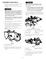
Remove and retain the existing discharge baffle and
mounting hardware as shown in Figure 3.
Note:
Retain the discharge baffle for reuse if the
mulch kit is removed.
G01801 1
1
Figure 3
1.
Existing discharge baffle
6.
Reinstall the mounting hardware, from step 5, into
the holes in the deck where the discharge baffle was
installed.
WARNING
Open holes in the mower expose you and
others to thrown debris which can cause
severe injury.
•
Never operate the mower without hardware
mounted in all holes in the mower housing.
•
Install the hardware in the mounting holes
when you remove the mulching baffle.
7.
Loosely install the baffle assembly to the RH side of
the mower deck using 5/16-18 x 3/4 inch carriage bolt
and two 5/16 inch flange nuts as shown in Figure 2 and
Figure 4.
G018012
1
2
3
4
1
Figure 4
Discharge deflector removed for clarity
1.
5/16 inch flange nut
3.
5/16-18 x 3/4 inch carriage
bolt
2.
Baffle assembly
4.
Welded post
8.
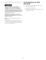
Remove the two plug bolts and nuts from the deck as
shown in Figure 5.
G018650
1
2
3
Figure 5
1.
Kicker plate
3.
Remove plug bolts and
nuts
2.
5/16 inch flange nut
9.
Secure the kicker plate to the LH side of the mower
deck using four 5/16 inch flange nuts as shown in
Figure 2 and Figure 5.
10.
Tighten all hardware.
3


