background image

- 23 -

a)

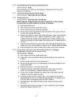
Disengage blade clutch.

b)

Stop engine and remove spark plug wire(s).

c)

Raise deck and block up using proper safety precautions.

d)

Clean out any grass build-up from underside of deck and in deck
discharge chute.

e)

Inspect blades and sharpen or replace as required.

f)

If blade removal is necessary, be careful for the sharp cutting edges of
the blades.

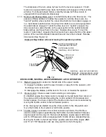
g)

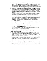
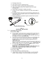
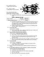
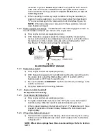
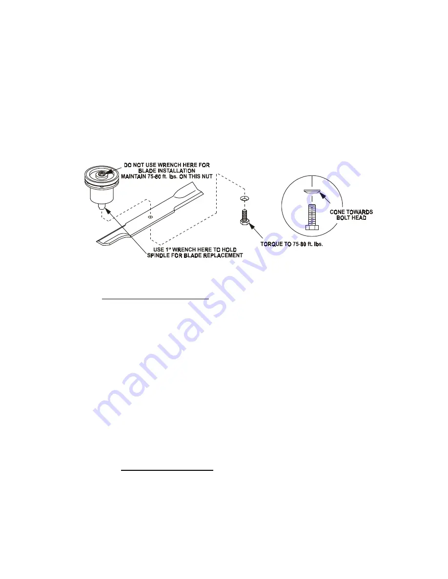
Re-install the blades (if they were removed) and torque blade bolts to 75-
80 ft. lbs. Be sure the spring disc washer cone is installed toward the bolt
head (See Figure 13).

h)

Remove jack stands (or equivalent support) and lower deck to ground.

FIG. 13

BLADE BOLT INSTALLATION

5.1.4

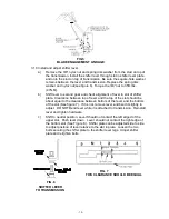
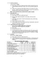
Check safety interlock system.

Service Interval:  

Daily

a)

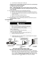
For your safety, your Exmark mower is equipped with Operator Presence
Controls (OPC).  When either the mower blades are engaged, or the
transmission shift lever is not in neutral and both hands are removed from
the handles, the mower engine 

MUST stop.

b)

Check OPC circuits. Clear the area. Run engine at one-third throttle, then
with drive levers and neutral lock/park brake latches in 

“park brake”

position

, Shift the transmission into gear and release OPC levers –

engine MUST stop.

Again, run engine at one-third throttle, move the transmission shifter lever to

neutral

, engage blade clutch and release OPC levers - 

engine MUST stop.

c)

If machine does not pass any of these tests, 

DO NOT 

operate. Contact

your authorized 

EXMARK SERVICE DEALER.

IMPORTANT:  It is essential that all Operator Safety Mechanisms, be
in place and in proper operating condition prior to mowing.

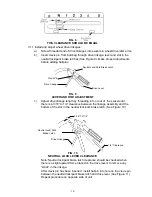
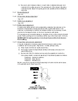
5.1.5 Check for loose hardware.

Service Interval:  

Daily

a)

Stop engine and remove spark plug wire(s).

b)

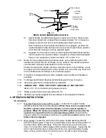
Visually inspect machine for any loose hardware or any other possible
problem. Tighten hardware or correct the problem before operating.

Summary of Contents for Metro HP MHP3614KA

Page 1: ...i ...

Page 2: ...justing servicing or performing maintenance If mower deck becomes clogged stop engine and remove spark plug wire s or remove key and wait for all moving parts to stop before cleaning blockage Keep hands feet and clothing away from power driven parts Keep off mower unless seat platform is provided Keep others off mower WARNING POTENTIAL HAZARD Gasoline is harmful or fatal if swallowed Long term exp...

Page 3: ...bmitting the Exmark Parts Plus order to Exmark by 3 00 p m central time the Distributor pays for the part and freight 3 Exmark being unable to ship the part and the Exmark parts order is received by 3 00 p m central time Exmark pays for the part and freight 4 If the part does not arrive overnight due to the shipper UPS the shipper pays for the freight and Exmark pays for the part The following res...

Page 4: ...wer maintain its maximum efficiency and promote safe operation If additional information is needed or should you require trained mechanic service contact your authorized Exmark equipment dealer or distributor All Exmark equipment dealers and distributors are kept informed of the latest methods of servicing and are equipped to provide prompt and efficient service in the field or at their service st...

Page 5: ...2 6 Transmission 9 2 7 Wheel Drive System 9 2 8 Tires 9 2 9 Deck 9 2 10 Dimensions 9 10 2 11 Torque Requirements 10 3 ASSEMBLY INSTRUCTIONS 3 1 to 3 18 Assembly 10 15 4 OPERATION INSTRUCTIONS 4 1 Controls 15 17 4 2 Pre Start 17 18 4 3 Operation Instructions 18 21 4 4 Transporting 21 5 MAINTENANCE ADJUSTMENTS 5 1 Periodic Maintenance 21 27 5 2 Adjustments 27 30 6 TROUBLE SHOOTING 6 1 Mower Pulling ...

Page 6: ...URY IF PROPER PRECAUTIONS ARE NOT TAKEN 1 2 TRAINING 1 2 1 Regard the Exmark mower as a piece of power equipment and teach this regard to all who operate this unit 1 2 2 Read the instructions carefully Familiarize yourself with the controls and the proper use of the equipment 1 2 3 Never allow children teenagers or people unfamiliar with these instructions to use the mower 1 2 4 Avoid mowing while...

Page 7: ...O AVOID THE HAZARD DO NOT smoke while refueling and stay away from an open flame or where gasoline fumes may be ignited by spark Refuel only in a well ventilated area or refuel outdoors Store gasoline in an approved container and keep it out of the reach of children Add fuel before starting the engine Never remove the cap of the fuel tank or add fuel when engine is running or when the engine is ho...

Page 8: ...pon the awareness concern prudence and proper training of the personnel involved in the operation transport maintenance and storage of the equipment It is essential that all Operator Safety Mechanisms be connected and in operating condition prior to use for mowing 1 4 1 Give complete undivided attention to the job at hand 1 4 2 Mow only in daylight or good artificial light Do Not operate the mower...

Page 9: ...ngine return the throttle control to the idle position for 30 seconds to allow the engine to cool down 1 4 14 The fuel system is provided with a shut off valve The fuel shut off valve is used to shut off the fuel when The machine will not be used for a few days During transport to and from the job When parking inside a building 1 4 15 This mower was designed for one operator only Keep all others a...

Page 10: ...supplied as original equipment 1 6 RIDING ATTACHMENTS 1 6 1 Use only Exmark riding attachments The use of other than Exmark riding attachments may create a hazardous condition resulting in injury 1 7 SAFETY SIGNS 1 7 1 Keep all safety signs legible Remove all grease dirt and debris from safety signs 1 7 2 Safety signs must be replaced if they are missing or illegible 1 7 3 When new components are ...

Page 11: ...os 190 000 Higher 15 17 HP Kawasaki PART NO 323699 LOCATION Console 15 17 HP Kawasaki PART NO 323691 LOCATION RH Side of Console PART NO 403005 LOCATION RH LH Corners of Mower Deck PART NO 303508 LOCATION Front of Mower Deck Top Surface PART NO 303293 LOCATION On Top RH Side of Fuel Tank 17HP Kawasaki 16HP B S Serial Nos 150 000 189 999 PART NO 403120 LOCATION On Switch Bracket at Front Left of Fu...

Page 12: ...r Deck Top Surface PART NO 513746 LOCATION On Engine Blower Housing next to Muffler on Center Belt Cover PART NO 323540 LOCATION Front of Mower Deck Top Surface PART NO 323550 LOCATION Upper Handle PART NO 303518 LOCATION Transmission Shifter Plate PART NO 413421 LOCATION Left Rear on Top of Engine Deck 16 HP Briggs Stratton PART NO 543631 LOCATION RH Side Console ...

Page 13: ...FETY INTERLOCK SYSTEM Operator must have transmission in neutral and blade clutch disengaged to start engine Release of OPC levers will cause the engine to stop if transmission is not in neutral and or blade clutch is engaged 2 5 STEERING BRAKE CONTROL Fingertip drive control levers provide independent speed control braking and neutral to each drive wheel for moving stopping and power turning Park...

Page 14: ...t with over center lock Belt tension is adjustable via turnbuckle 2 9 5 Deck Mounting Full floating deck is attached to out front support frame removable for service 2 9 6 Cutting Height Adjusts in 1 2 63 cm increments from 1 5 3 8 cm to 4 1 2 11 4 cm 2 10 DIMENSIONS 2 10 1 Overall Width 36 48 52 Discharge chute down 46 25 58 25 62 6 117 5 cm 148 0 cm 159 0 cm Discharge chute up 36 1 48 1 53 0 Tra...

Page 15: ...ith a 5 16 SAE flatwasher and 5 16 lockwasher into the threaded holes in the right side of the fuel tank Do not over tighten Place a 5 16 SAE flatwasher then a spring over each of the studs and fasten with a 5 16 nyloc nut Tighten 3 16 nylock nut fully then cack off a 1 2 turn This is to allow for normal fuel tank expansion with changes in temperature and fuel levels 3 6 Attach the fuel tank hose ...

Page 16: ...oosen clamp on engine control plate See Figures 2 3 4 Attach inner wire of the throttle cable to the control plate lever and position cable clamp do not tighten clamp FIG 2 KOHLER SPEED CONTROL THROTTLE CABLE HOOK UP FIG 3 14 HP KAWASAKI SPEED CONTROL THROTTLE CABLE HOOK UP FIG 4 15 17 HP KAWASAKI SPEED CONTROL THROTTLE CABLE HOOK UP Control Alignment Holes Control Plate Lever Choke Link Clamp Con...

Page 17: ...f the engine continues to run in the STOP position turn the kill switch adjusting screw inward until engine stops then give it an additional 1 2 to 3 4 turn to assure it will always function properly The 14 HP Kawasaki kill switch is not adjustable For 15 17 HP Kawasaki engines There is not a STOP position The engine will continue to run when the throttle control is moved past the rear detent Turn...

Page 18: ...ever and the top of the slot should be about equal to the clearance between bottom of the lever and the bottom of the slot See figure 7 If it is not remove lever and bend it slightly to adjust DO NOT Bend lever while it is attached to transmission Reinstall lever and tighten hardware c Shift to neutral position Lever Should not contact the left edged of the upper slot Push lever down Lever should ...

Page 19: ... 16 to 1 4 clearance between the linkage assembly and the bottom of the slot in the neutral lock park brake latch See Figure 10 FIG 10 NEUTRAL LOCK LEVER CLEARANCE Note Neutral lock park brake latch clearance should be checked when there is a slight upward force placed on the drive levers to remove any slack in the linkage After clevis pin has been inserted install hairpin into hole on the clevis ...

Page 20: ...ll debris guard to top of engine 3 15 Service Engine Refer to Engine Owner s Manual 3 16 GREASE UNIT NOTE UNIT IS NOT GREASED AT THE FACTORY Refer to 5 1 13 for locations and grease amounts 3 17 Follow pre start instructions as outlined in 4 2 3 18 Perform any needed adjustments as outlined in the Adjustment Section 4 OPERATION INSTRUCTIONS 4 1 Controls 4 1 1 Operator Presence Control OPC Levers L...

Page 21: ...le To engage the blades push the lever forward or away from the operator until the linkage locks over center To disengage the blades pull the lever to the rear or towards the operator 4 1 5 Choke Control Choke is used to aid in starting a cold engine On the B S engine the choke control is located on the left hand front corner of the engine and is activated by pulling the control outward On Kawasak...

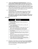
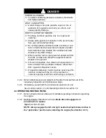
Page 22: ...ackward to assist with the movement of the unit 4 2 Pre Start DANGER POTENTIAL HAZARD In certain conditions gasoline is extremely flammable and highly explosive WHAT CAN HAPPEN A fire or explosion from gasoline can burn you others and cause property damage HOW TO AVOID THE HAZARD DO NOT smoke while refueling and stay away from an open flame or where gasoline fumes may be ignited by spark Refuel on...

Page 23: ... If this is not possible then refuel such equipment on a truck or trailer from a portable container rather than from a gasoline dispenser nozzle If a gasoline dispenser nozzle must be used keep the nozzle in contact with the rim of the fuel tank or container opening at all times until fueling is complete 4 2 2 Refer to Maintenance and Adjustment Section 5 and perform all of the necessary inspectio...

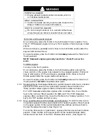
Page 24: ...engine With a cold engine gradually return choke to the full throttle position after the engine starts and warms up On a warm engine place the throttle control midway between the Slow and Fast positions DO NOT choke B S when warm 4 3 3 Stopping Engine Disengage blade drive position speed control lever in neutral and lock the drive levers in the park brake position Move throttle to the Slow positio...

Page 25: ...ock park brake latches from the neutral or park brake position For straight ahead motion smoothly release both drive levers to engage drive wheels Squeeze the right hand drive lever to turn right and the left hand drive lever to turn left See Section 4 1 2 4 3 6 To Stop Squeeze drive levers back to engage brakes Move neutral lock park brake latches into the park brake position and release drive le...

Page 26: ...use assistance when loading Use a heavy duty trailer to transport the machine Engage park brakes and block wheels Securely fasten the machine to the trailer with straps chains cables or ropes Do not rely solely on parking brake to hold machine on trailer Use a safety chain and be sure that the trailer has all necessary lighting and marking as required by law 5 MAINTENANCE ADJUSTMENTS 5 1 PERIODIC ...

Page 27: ...al to bring the oil level up to the F mark on the dipstick DO NOT OVERFILL IMPORTANT DO NOT operate the engine with oil level below the L mark or over the F mark 5 1 2 Clean engine air cooling system Service Interval See Engine Owner s Manual a Stop engine and remove spark plug wire s b Clean all debris from engine air intake screen and from around engine shrouding 5 1 3 Clean grass build up under...

Page 28: ...wer blades are engaged or the transmission shift lever is not in neutral and both hands are removed from the handles the mower engine MUST stop b Check OPC circuits Clear the area Run engine at one third throttle then with drive levers and neutral lock park brake latches in park brake position Shift the transmission into gear and release OPC levers engine MUST stop Again run engine at one third th...

Page 29: ... specified capacity and replace cap Use oil as specified in Engine Owners Manual Do not overfill g Start the engine and check for leaks Stop engine and recheck oil levels 5 1 9 Check grease level input and output shaft bearing wear on Peerless Transmission Replace gearbox grease yearly Service Interval 160 hrs a Stop engine and remove spark plug wire s b Place drive levers and neutral lock park br...

Page 30: ...every 2 hrs for first 8 hrs operation then check every 40 hrs thereafter a Stop engine b Engage blade drive lever c Look through the round hole in the left rear corner of the engine deck to inspect blade clutching belt tension Bolt on blade engagement linkage bellcrank and indicator arm should align within 1 16 See fig 15 Refer to section 5 2 2 for adjustment 5 1 13 Lubrication Service Interval Re...

Page 31: ...replace with new plugs See Engine Owner s Manual 5 1 15 Remove engine shrouds and clean cooling fins Service Interval See Engine Owner s Manual a Stop engine and remove spark plug wire s b Remove cooling shrouds from engine and clean cooling fins Also clean dust dirt and oil from external surfaces of engine which can cause improper cooling c Make sure cooling shrouds are properly reinstalled Opera...

Page 32: ...s of contact 5 2 ADJUSTMENTS 5 2 1 Cutting height and anti scalp roller adjustment WARNING POTENTIAL HAZARD When the two front support rod hairpins are removed from the mower deck the weight of the tractor section may cause the front frame to rise suddenly WHAT CAN HAPPEN If the unit rises suddenly injury may occur HOW TO AVOID THE HAZARD Securely hold down the front of the unit when the front sup...

Page 33: ...ocknut against turnbuckle FIG 15 BLADE ENGAGEMENT LINKAGE 5 2 3 Blade Safety Switch a Stop engine and remove spark plug wire s b With blades disengaged and the bellcrank touching the rear of the slot in the engine deck adjust the blade safety switch if needed until the bellcrank arm is 5 16 from the switch body c Be sure the bellcrank DOES NOT touch the switch body or damage to the switch could oc...

Page 34: ...ise to decrease force on lever required to shift gears Factory setting is to turn setscrew all the way in then back out 1 1 2 turns IMPORTANT Screwing setscrew in too far will prevent the transmission from shifting 5 2 11 Wheel drive spring tension adjustment It may be necessary to increase wheel drive belt tension under certain conditions such as wet grass hilly terrain or while pulling a sulky a...

Page 35: ...ion on each support pin c Check deck support alignment and check mounting brackets to be sure all bolts are tight d Check blades tip to tip for straightness They should be within 3 16 or one blade width from being in line 6 3 ENGINE WILL NOT START a Check that choke is in the ON position for a cold engine or in the OFF position for a warm engine See 4 3 2 NOTE Kawasaki engines may need to be choke...

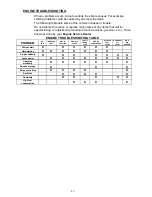
Page 36: ...such as valves governor etc Have this work done by your Engine Service Dealer ENGINE TROUBLESHOOTING TABLE PROBLEM NO FUEL IMPROPER FUEL DIRT IN FUEL LINE DIRTY AIR FILTER FAULTY SPARK PLUG ENGINE OVERLOADED BLOCKED FUEL FILTER INCORRECT OIL LEVEL DIRTY AIR SCREEN Will not start X X X X X X Hard starting X X X X X X X Stops suddenly X X X X X X X Lacks power X X X X X X X X Operates erratically X ...

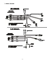
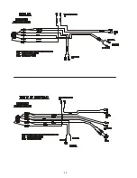
Page 37: ... 32 7 WIRING DIAGRAM ...

Page 38: ... 33 ...

Page 39: ...ponsibility in respect to claims is limited to making the required repairs or replacements and no claim of breach of warranty shall be cause for cancellation or rescission of the contract of sale of any Exmark mower Proof of purchase may be required by the dealer to substantiate any warranty claim All warranty work must be performed by an authorized Exmark service dealer This warranty extends only...

Page 40: ... vii any claims for lost revenue lost profit or additional cost as a result of a claim of breach of warranty or viii attorney s fees There are no representations or warranties which have been authorized and provided to the buyer of the turf equipment other than as set forth in this warranty Any and all statements or representations made by any seller of this equipment including those set forth in ...

Page 41: ... 36 SERVICE RECORD Date Description of Work Done Service Done By ...

Page 42: ... 37 NOTES ...

Page 43: ...L O P E T H IS I S A 1 0 S L O P E T H IS IS A 5 S LO P E ALIGN THIS EDGE WITH A VERTICAL SURFACE TREE BUILDING FENCE POST POLE ETC EXAMPLE COMPARE SLOPE WITH FOLDED EDGE FOLD ALONG APPROPRIATE LINE T H I S I S A 2 0 S L O P E ...

Page 44: ...R TURF TRACER TURF TRACER HP VIKING HYDRO METRO METRO HP SELF STEERING SULKY GRASS CATCHER MICRO MULCH ACCESSORY M F G C O IN C 1997 1998 1999 PART NO 850662 EXMARK MFG CO INC 402 223 6300 INDUSTRIAL PARK BOX 808 FAX 402 223 5489 BEATRICE NE 68310 ALL RIGHTS RESERVED PRINTED IN U S A ...

Reviews: