


Operation
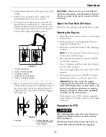
To turn right, release pressure on the RH motion
control lever and the rear of the machine will
move towards the rear and to the right.
To turn left, release pressure on the LH motion
control lever and the rear of the machine will
move towards the rear and to the left.
3. To stop, position both motion control levers in
the neutral operate position.
Adjusting the Cutting Height
The cutting height of the mower deck is adjusted
from 1 1/2 to 4 1/2 inches (3.8 cm to 11.4 cm) in 1/4
inch (6.4 mm) increments.
1. Stop the machine and move the motion control
levers outward to the neutral locked position.
2. Disengage the PTO.
3. Position the transport lock in the latching
position.
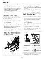
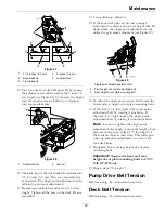
4. Raise and lock the deck to the 4 1/2 inch (11.4
cm) transport position (Figure 16).
The deck is raised by pushing the foot operated
deck lift pedal forward. The pedal is located at the
front right corner of the floor pan.
Note:
When changing the cutting height
positions, always come to a complete stop
and disengage the PTO.
Figure 16
1.
Deck lift foot pedal
3.
Height of cut decal
2.
Height adjustment pin
4.
Transport lock control
5. Insert the height adjustment pin into the hole
corresponding to the desired cutting height.
See the decal on the side of the deck lift plate for
cut heights.
6. Push the deck lift pedal, release the transport lock
and allow the deck to lower to the cutting height.
Adjusting the Deck Lift Foot Pedal —
48 & 52 inch Decks Only
The deck lift foot pedal can be adjusted for operator
comfort.
1. Stop the machine and move the motion control
levers outward to the neutral locked position.
2. Disengage the PTO.
3. Engage the park brake.
4. Stop the engine, remove the key and wait for all
moving parts to stop.
5. Position the transport lock in the latching
position.
6. Raise and lock the deck to the 4 1/2 inch (11.4
cm) transport position (Figure 16).
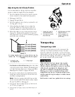
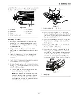
7. Remove the two nuts from the deck lift foot pedal
(see Figure 17).
Figure 17
1.
Deck lift foot pedal
4.
Hole set that moves
the pedal closer to the
operator
2.
Nuts
5.
Hole set that moves the
pedal away from the
operator
3.
Adjustment holes
6.
Adjusts the pedal higher
or lower
8. Position the deck lift pedal for operator comfort
and reinstall the nuts. Tighten hardware.
26
Summary of Contents for LAZER Z E-SERIES Operators
Page 1: ...LAZER Z E SERIES For Serial Nos 312 000 000 Higher Lazer Z LZE Units Part No 4501 202 Rev A ...
Page 53: ...Schematics Hydraulic Diagram 53 ...
Page 55: ...Notes 55 ...
Page 56: ...Notes 56 ...
Page 57: ...Service Record Date Description of Work Done Service Done By 57 ...
Page 58: ...58 ...


