background image

Specifications

Mounting: Hinged to tilt up for access to
hydraulic pumps, battery and other components.
Held in tilted position with scissor—type links.
Adjustable fore and aft seat track.

Armrests: Molded adjustable flip-up armrests.

Seat Safety Switch: Integrated seat switch.
Time delay seat switch eliminates rough ground
cut-outs.

Hydrostatic Ground Drive System

Hydrostatic Pumps: Two Hydro Gear PW
variable displacement piston pumps.

Wheel Motors: Two Parker/Ross with 1 1/4 inch
tapered shafts.

Hydraulic Oil Type: Exmark Premium Hydro oil.

Hydraulic Oil Capacity: 5.5 qt. (5.2 L)

Hydraulic Filter: Replaceable cartridge type.

P/N 103-2146: 25 microns, No bypass

Speeds:

– 0-12.0 mph (19.3 km/hr) forward.

– 0-8.0 mph (12.9 km/hr) reverse.

Drive wheel release valves allow machine to be
moved when engine is not running.

Tires & Wheels

Drive — All Units

Type

Pneumatic (Air-Filled)

Quantity

2

Tread Size

“Multi-Trac C/S”

Size

26 x 12.00-12

Ply Rating

4

Pressure

10 psi (69 kPa)

Front Caster

Side Discharge

Rear Discharge

Type

Semi-Pneumatic

Semi-Pneumatic

Quantity

2

2

Tread Size

Smooth

Smooth

Size

13 x 6.50-6

15 x 6.00-6

Cutting Deck

Cutting Width:

– 60 inch (152.4 cm)

– 72 inch (182.9 cm)

Discharge: Side or Rear

Blade Size: (3 ea.)

– 60 inch Deck: 20.75 inches (52.7 cm)

– 72 inch Deck: 24.75 inches (62.9 cm)

Blade Spindles: Solid steel spindles with 1.18 inch
(30 mm) I.D. bearings.

Deck Drive:

– Electric clutch mounted on horizontal engine

shaft. “B” Section belt (with self-tensioning
idler) from electric clutch to deck.

– Blades Driven By:

◊ Side Discharge: One “B” Section belt

(w/self-tensioning idler) from transfer
shaft on deck to blade spindles.

◊ Rear Discharge: One “B” Section belt

(w/self-tensioning idler) from electric
clutch to center and LH blade spindles.
RH spindle is driven by one “B” Section
hex belt (w/self-tensioning idler) from the
center blade spindle.

Deck:

– Side Discharge: Full floating deck is attached

to out-front support frame. Six anti-scalp
rollers provide maximum turf protection.
Deck design allows for bagging, mulching or
side discharge.

– Rear Discharge: Full floating deck is attached

to out-front support frame. Four anti-scalp
rollers and side bumpers provide maximum
turf protection. Deck design allows for rear
discharge or finish cut (reduced discharge).

Deck Depth:

– Side Discharge: 6.0 inches (15.2 cm)

– Rear Discharge: 5.5 inches (14.0 cm)

Cutting Height Adjustment:

An extra-long cushioned lever is used to adjust
the cutting height:

– Side Discharge: from 1 inch (2.5 cm) to

5 inches (12.7 cm) in 1/4 inch (6.4 mm)
increments.

– Rear Discharge: from 1 1/2 inches (3.8 cm)

to 5 inches (12.7 cm) in 1/4 inch (6.4 mm)
increments.

19


Summary of Contents for LAZER Z DS Series

Page 1: ...LAZER Z DS SERIES For Serial Nos 400 000 000 Higher Part No 4503 187 Rev B ...

Page 2: ... Engine Service Dealer This spark ignition system complies with the Canadian standard ICES 002 Ce système d allumage par ètincelle de vèhicule est conforme à la norme NMB 002 du Canada Please refer to the engine manufacturer s information included with the machine Labeled power ratings are supplied by the engine manufacturer in accordance with SAE testing and gross net power rating standards J1940...

Page 3: ...com for additional safe operation information such as safety tips training materials and Operator s manuals If additional information is needed or should you require trained mechanic service contact your authorized Exmark equipment dealer or distributor All Exmark equipment dealers and distributors are kept informed of the latest methods of servicing and are equipped to provide prompt and efficien...

Page 4: ...ol Bronze Bushings 42 Drain Fuel Filter Water Separator 42 Change Fuel Filter Water Separator 42 Change Hydraulic System Filter and Fluid 42 Check Engine Coolant Level 43 Change Engine Coolant 43 Check Spark Arrester if equipped 44 Thread Locking Adhesives 45 Mobil HTS Grease Or Food Grade Anti seize 45 Copper Based Anti seize 45 Dielectric Grease 45 Adjustments 46 Deck Leveling 46 Pump Drive Belt...

Page 5: ...can not read this manual it is the owner s responsibility to explain this material to them other languages may be available on our website Become familiar with the safe operation of the equipment operator controls and safety signs All operators and mechanics should be trained The owner is responsible for training the users Never let children or untrained people operate or service the equipment Loc...

Page 6: ... exhaust system in place and in proper working condition DANGER In certain conditions during fueling static electricity can be released causing a spark which can ignite fuel vapors A fire or explosion from fuel can burn you and others and cause property damage Always place fuel containers on the ground away from your vehicle before filling Do Not fill fuel containers inside a vehicle or on a truck...

Page 7: ...king brake Before checking cleaning or working on the mower After striking a foreign object or abnormal vibration occurs inspect the mower for damage and make repairs before restarting and operating the mower Before clearing blockages Whenever you leave the mower Stop engine wait for all moving parts to stop and engage parking brake Before refueling Before dumping the grass catcher WARNING Hands f...

Page 8: ...t grass across steep slopes or downhill may cause the mower to lose traction Loss of traction to the drive wheels may result in sliding and a loss of braking and steering Always avoid sudden starting or stopping on a slope If tires lose traction disengage the blades and proceed slowly off the slope Follow the manufacturer s recommendations for wheel weights or counter weights to improve stability ...

Page 9: ...e Do Not make adjustments with the engine running Charge batteries in an open well ventilated area away from spark and flames Unplug charger before connecting or disconnecting from battery Wear protective clothing and use insulated tools DANGER Charging or jump starting the battery may produce explosive gases Battery gases can explode causing serious injury Keep sparks flames or cigarettes away fr...

Page 10: ...hands to find hydraulic leaks Safely relieve all pressure in the hydraulic system by placing the motion control levers in neutral and shutting off the engine before performing any work on the hydraulic system WARNING Fuel system components are under high pressure The use of improper components can result in system failure fuel leakage and possible explosion Use only approved fuel lines and fuel fi...

Page 11: ... off the backing to expose the adhesive surface Apply only to a clean dry surface Smooth to remove any air bubbles Familiarize yourself with the following safety signs and instruction labels They are critical to the safe operation of your Exmark commercial mower 93 6687 1 Do not step here 106 2733 1 Fast 3 Slow 2 Continuous variable setting 106 5517 1 Warning do not touch the hot surface 107 3069 ...

Page 12: ...he Operator s Manual for instructions on torquing the blade bolt nut to 55 60 ft lb 75 81 N m 116 8598 Rear Discharge Units Only 117 2718 120 0625 1 Pinch point hand keep hands away 126 2055 1 Wheel lug nut torque 95 ft lb 129 N m 4x 2 Wheel hub nut torque 235 ft lb 319 N m 3 Read and understand the Operator s manual before performing any maintenance check torque after first 100 hours then every 5...

Page 13: ... parts keep all guards in place Stop engine and remove key before adjusting servicing or cleaning 5 Warning Disengage PTO move drive levers out to neutral lock position engage parking brake and stop engine before leaving the operator s position 126 4756 1 Cutting dismemberment of hand or foot stay away from moving parts keep all guards and shields in place 2 Thrown object hazard Pick up objects th...

Page 14: ... and read the instructions before servicing or performing maintenance 3 Height of cut 126 4758 Side Discharge Units Only 126 4759 1 Start relay 4 Oil pressure relay 2 Fan relay 5 Charge relay 3 Glow relay 126 4760 Pump Belt Routing 126 4762 1 PTO kill relay 2 PTO relay 14 ...

Page 15: ...g this machine 7 See engine owner s manual for service 2 Check engine oil every 8 hours 8 Check hydraulic oil level Only use recommended hydro oil every 40 hours 3 Check tire pressure 10 psi 2x every 40 hours 9 Grease belt idlers 3x every 500 hours 4 Grease brake brackets 2x every 200 hours 10 Grease deck struts 2x every 40 hours 5 Grease deck lift pivot every 40 hours 11 Grease deck pivots 4x eve...

Page 16: ...ng dismemberment of hand or foot stay away from moving parts keep all guards and shields in place 2 Thrown objects hazard mower do not operate without the deflector discharge cover or grass collection system in place 126 6599 Rear Discharge Units 1 Thrown objects hazard keep bystanders a safe distance from the machine 2 Cutting dismemberment of hand stay away from moving parts keep all guards and ...

Page 17: ...Ramp hazard when loading onto a trailer do not use dual ramps only use a singular ramp wide enough for the machine and that has an incline less than 15 degrees back up the ramp in reverse and drive forward off the ramp 2 Cutting and pinching hazard keep hands and feet away from moving parts keep all guards and shields in place 5 Bodily harm hazard look behind you when mowing in reverse 3 Thrown ob...

Page 18: ... temperature gauge will be in the red area when the engine temperature reaches an overheat condition The PTO will not re engage until the engine has cooled and the PTO switch is manually shut off and re engaged Note If the engine coolant level is below the indicator line on the overflow bottle when the engine is cold the coolant temperature gauge may not register correctly during operation and or ...

Page 19: ...ade Size 3 ea 60 inch Deck 20 75 inches 52 7 cm 72 inch Deck 24 75 inches 62 9 cm Blade Spindles Solid steel spindles with 1 18 inch 30 mm I D bearings Deck Drive Electric clutch mounted on horizontal engine shaft B Section belt with self tensioning idler from electric clutch to deck Blades Driven By Side Discharge One B Section belt w self tensioning idler from transfer shaft on deck to blade spi...

Page 20: ...nch Deck 72 inch Deck Roll Bar Up 81 9 inches 208 0 cm 85 8 inches 217 9 cm Roll Bar Down 92 5 inches 235 0 cm 96 4 inches 244 9 cm Rear Discharge Units 60 inch Deck 72 inch Deck Roll Bar Up 85 6 inches 217 5 cm 89 8 inches 228 1 cm Roll Bar Down 96 2 inches 244 4 cm 100 4 inches 255 0 cm Overall Height All Units All Units cont d Roll Bar Up Roll Bar Down 72 7 inches 184 7 cm 53 8 inches 136 7 cm ...

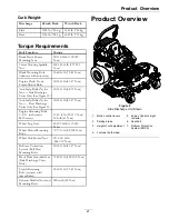
Page 21: ...e Figure 13 30 35 ft lb 41 47 N m Engine Mounting Bolts 1 2 13 inch screws M10 screws 67 83 ft lb 99 113 N m 30 ft lb 41 N m Wheel Lug Nuts 85 105 ft lb 115 142 N m Wheel Motor Mounting Bolts 72 77 ft lb 98 104 N m Wheel Hub Slotted Nut 211 260 ft lb 286 352 N m Rollover Protection System Roll Bar Mounting Bolts 30 35 ft lb 41 47 N m Deck Drive Jackshaft Nut Side Discharge Units Only 75 80 ft lb 1...

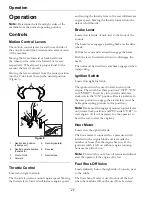
Page 22: ...arking brake on the drive wheels Pull the lever up and rearward to engage the brake Push the lever forward and down to disengage the brake The unit must be tied down and brake engaged when transporting Ignition Switch Located on right fuel tank The ignition switch is used to start and stop the engine The switch has three positions OFF ON and START Insert key into switch and rotate clockwise to the...

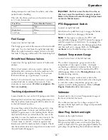
Page 23: ...tracks straight Check that the machine does not creep when in neutral with the park brake disengaged Important Do Not rotate the knob too far as this may cause the machine to creep in neutral Refer to the Motion Control Linkage Adjustment section in Maintenance PTO Engagement Switch Located on right fuel tank Switch must be pulled out up to engage the blades Switch is pushed in to disengage the bl...

Page 24: ...point characteristics therefore easing startability and lessening chances of chemical separation of the fuel due to lower temperatures wax appearance which may plug filters Use of summer grade diesel fuel above 20 F 7 C will contribute toward longer life of the pump components Important Do Not use kerosene or gasoline instead of diesel fuel Failure to observe this caution will damage the engine Do...

Page 25: ...e fuel left over from summer 7 Turn ignition switch to the ON position Depress the glow plug switch and the glow plug light will turn on Hold switch as required by chart below Turn the ignition switch to the START position Release the ignition switch as soon as the engine starts Glow Plug Chart Ambient Temperature Hold Glow Plugs On Above 50 F 10 C NO NEED 50 F 10 C to 23 F 5 C Approximately 5 sec...

Page 26: ...e to run for a minimum of 15 seconds then turn the ignition switch to the OFF position to stop the engine 7 Remove the key to prevent children or other unauthorized persons from starting engine 8 Close the fuel shut off valve when the machine will not be in use for a few days when transporting or when the unit is parked inside a building Driving the Machine CAUTION Machine can spin very rapidly by...

Page 27: ...o the left 3 To stop position both motion control levers in the neutral operate position Adjusting the Cutting Height The cutting height of the mower deck is adjusted from 1 to 5 inches 2 54 cm to 12 7 cm in 1 4 inch 6 4 mm increments on side discharge units and 1 1 2 inches 3 8 cm to 5 inches 12 7 cm in 1 4 inch 6 4 mm increments on rear discharge units 1 Stop the machine and move the motion cont...

Page 28: ...e rollers in one of the positions shown Figure 11 Rollers will maintain 3 4 inch 19 mm clearance to the ground to minimize gouging and roller wear or damage Figure 11 For cutting heights above 4 0 inches 102 mm use the bottom hole The rollers will still be effective against scalping 1 Anti scalp roller mounting bracket 2 Cutting height For Maximum Deck Flotation place the rollers one hole position...

Page 29: ...position 6 Remove the bolts and nuts from each bumper Figure 14 1 Bolt 3 Nut 2 Bumper 7 Move each bumper to the desired position and secure them with the bolts and nuts Note Only use the top or center sets of holes to adjust the bumpers The bottom holes are used when switching sides at which time they become the top holes on the other side of the mower Transporting Transporting the Machine Use a h...

Page 30: ...ves from the ramp to the trailer or truck Steeper angles may also cause the machine to tip or lose control If loading on or near a slope position the trailer or truck so that it is on the down side of the slope and the ramp extends up the slope This will minimize the ramp angle WARNING Loading a machine onto a trailer or truck increases the possibility of tip over and could cause serious injury or...

Page 31: ...stowed position 4 Ramp is at least four times 4X as long as the height of the trailer or truck bed to the ground 2 Side view of full width ramp in loading position 5 H height of the trailer or truck bed to the ground 3 Not greater than 15 degrees 6 Trailer 31 ...

Page 32: ...re each use or daily Check the engine oil level Check the mower blades Check the safety interlock system Check the rollover protections systems roll bar pins Check the seat belt Check for loose hardware Check engine coolant level Clean the engine cooling system Clean the engine and exhaust system area Clean the grass and debris build up from the machine and cutting deck Clean the grass build up fr...

Page 33: ...the notch the radiator may fall Falling radiator could cause serious injury Be sure the prop rod is engaged securely in the notch at the far right side of the slot 4 Clean area around dipstick Remove dipstick and wipe oil off Reinsert the dipstick and push it all the way down into the tube Remove the dipstick and read the oil level 5 If the oil level is low wipe off the area around the oil fill ca...

Page 34: ... engine may occur DANGER Jump starting a weak battery that is cracked frozen has low electrolyte level or an open shorted battery cell can cause an explosion resulting in serious personal injury Do Not jump start a weak battery if these conditions exist 2 Make sure the booster is a good and fully charged lead acid battery at 12 6 volts or greater Use properly sized jumper cables 4 to 6 AWG with sh...

Page 35: ... Clean Grass Build Up Under Deck procedure 3 Inspect blades and sharpen or replace as required 4 Reinstall the blades if they were removed in the following order A Install bushing through blade with bushing flange on bottom grass side of blade Figure 19 Blade on Side Discharge Unit Shown 1 Install bushing in blade prior to installing bushing in spindle B Install bushing blade assembly into spindle...

Page 36: ... Service Interval Before each use or daily Important It is essential that operator safety mechanisms be connected and in proper operating condition prior to use Note If machine does not pass any of these tests Do Not operate Contact an Authorized Service Dealer Note To prevent engine cut outs on rough terrain the seat has a 1 2 second time delay before the engine begins to shutdown Check the Norma...

Page 37: ...Parking Brake PTO Blades Motion Control Levers Operator Outcome Engaged Disengaged Both levers moved in or either right or left lever moved in Operator in seat Starter must not crank Disengaged Disengaged Both levers out neutral lock Operator in seat Starter must not crank Engaged Engaged Both levers out neutral lock Operator in seat Starter must not crank State of System 37 ...

Page 38: ...al lock both levers moved in or either right or left lever moved in Raise off of seat but don t get off Engine must begin shutdown within 1 second Running idle 1 3 throttle Disengaged Engaged Both levers moved in Raise off of seat but don t get off Engine must begin shutdown within 1 second Running idle 1 3 throttle Engaged Disengaged Both levers moved in or either right or left lever moved in Ope...

Page 39: ...ase around the inner element before removing so dirt does not get into the engine 6 Do Not wash or use pressurized air to clean paper element or inner element 7 Reinstall elements Position the cover so that the rubber dust ejector is pointing downward and secure with retaining clips Change Engine Oil Service Interval After the first 5 hours Every 100 hours Yearly whichever comes first May need mor...

Page 40: ...tires may cause failures to the hydro drive system frame and other components Foam filling tires will void the warranty Check Condition Of Belts Service Interval Every 40 hours 1 Stop engine wait for all moving parts to stop and remove key Engage parking brake 2 Unhook seat latch and tilt seat up Remove the air detector panel on front side of the engine compartment to check pump drive belt and alt...

Page 41: ...applied to lock the spacer nuts to the axle Remove the axle with the other spacer nut still assembled to it from the wheel assembly 5 Pry out seals and inspect bearings for wear or damage and replace if necessary 6 Pack the bearings with a NLGI grade 1 multi purpose grease 7 Insert one bearing one new seal into the wheel Note Seals Exmark P N 103 0063 must be replaced 8 If the axle assembly has ha...

Page 42: ...urs 1 Stop engine wait for all moving parts to stop and remove key Engage parking brake 2 Unhook seat latch and tilt seat up 3 Lubricate bronze bushings on flange bearings securing the motion control arm shafts with a light oil or a spray type lubricant Drain Fuel Filter Water Separator Service Interval Every 40 hours 1 Stop engine wait for all moving parts to stop and remove key Engage parking br...

Page 43: ... or been extremely hot Changing oil unnecessarily could damage hydraulic system by introducing contaminates into the system Check Engine Coolant Level Service Interval Before each use or daily Note If the engine coolant level is below the indicator line on the overflow bottle when the engine is cold the coolant temperature gauge may not register correctly during operation and or the warning buzzer...

Page 44: ...mately 1 2 inch 12 7 mm for expansion Add 50 50 coolant mix to overflow bottle on the left side of the engine as required to bring the level up to the indicator line on the bottle WARNING Engine compartment contains open belt drives fans and other rotating components that can cause injury Fingers hands loose clothing or jewelry can get caught by the rotating fan and drive shaft Do Not operate mach...

Page 45: ...ws Square head setscrews on Hydro pump control arms Sheave retaining bolt in the end of engine crankshaft Caster wheel spacer nuts Fuel tank bulkhead fitting nuts Bolts retaining stub shaft to engine flywheel Adhesives such as Loctite RC 609 or RC 680 or Fel Pro Pro Lock Retaining I or Retaining II are used on the following Fuel tank studs where studs are inserted into tank Mobil HTS Grease Or Foo...

Page 46: ...ont center anti scalp roller brackets 8 Loosen the two top chain bolts in slots in the rear deck lift arms Loosen jam nuts and back off the socket head adjusting screws on the bottom of the arms until the chains are just loose Turn the socket head adjusting screws in until slack is taken out of each chain Tighten the jam nuts Tighten the chain bolts in the deck lift arms making sure they don t mov...

Page 47: ...ters of the two alignment slots in the left support plate Figure 24 and Figure 25 It is necessary to adjust the belt tension when the center of the bolt head is at or below the center of the bottom alignment hole 3 When adjustment is necessary loosen the idler pulley on the right hand side so it can move up and down in the slot Place a wrench on the 3 8 inch nut in the center of the spring loaded ...

Page 48: ... 3 Note belt guide bolted to deck near the shield support stud and right hand pulley Guide should be 1 8 inch 3 2 mm away from the belt with bolt end of guide near end of slot Figure 27 4 If adjustment is necessary loosen the bolt securing the belt guide and make proper adjustment Tighten hardware Figure 27 1 End of slot 2 Belt guide Parking Brake Adjustment Service Interval After the first 100 ho...

Page 49: ...til the correct gap can be achieved 13 If a brake component has been removed or replaced see the steps below otherwise proceed to step 14 Burnishing the Brake Procedure A Clear the area of any flammable material before starting the burnishing process B While sitting in the operator s seat start the engine and release the park brake WARNING Engine must be running and drive wheels must be turning so...

Page 50: ... brake mounting bolts one half to one full turn see Figure 30 Note Do Not remove the brake pole from the field shell armature The brake pole has worn to match the armature and needs to continue to match after the shim is removed to ensure proper brake torque Figure 30 1 Brake mounting bolt 2 Shim B Using needle nose pliers or by hand take hold of the tab and remove the shim Do Not discard the shim...

Page 51: ...l lever back until the clevis pin on arm below pivot shaft contacts the end of the slot just beginning to put pressure on spring Figure 33 4 Check where lever is relative to notch in console should be centered allowing lever to pivot outward to the neutral lock position 5 If adjustment is needed loosen the nut against the yoke and while applying slight rearward pressure on the motion control lever...

Page 52: ...being used Run engine at full throttle and release brake 7 The reverse indicator spring must be correct before the following adjustments can be made See the Reverse Indicator Adjustment section Note The motion control lever needs to be in neutral while making any necessary adjustments The left rod assembly controls the left wheel and the right rod assembly controls the right wheel 8 Bring the moti...

Page 53: ... 4 Most resistance firmest feel 5 Torque nyloc nut to 200 in lb 16 7 ft lb Bolt must protrude past end of nyloc nut after torque 6 Damper 7 Damper must move freely on bolt Caster Pivot Bearings Pre Load Adjustment Remove dust cap from caster and tighten nyloc nut until washers are flat and back off 1 4 of a turn to properly set the pre load on the bearings If disassembled make sure the spring disc...

Page 54: ... a fire hazard Clean all debris from engine and exhaust system area 1 Stop engine wait for all moving parts to stop and remove key Engage parking brake 2 Remove air deflector panel from behind seat 3 Clean around flywheel cylinder head injectors and injector pump 4 Clean all debris from the exhaust system area 5 Wipe up any excessive grease or oil around the engine and exhaust area 6 Reinstall the...

Page 55: ...rt Use adequate jack stands or equivalent support 3 Clean out any grass build up from underside of deck and in discharge deflector Waste Disposal Motor Oil Disposal Engine oil and hydraulic oil are both pollutants to the environment Dispose of used oil at a certified recycling center or according to your state and local regulations Battery Disposal DANGER Battery electrolyte contains sulfuric acid...

Page 56: ...h is defective 7 Contact an Authorized Service Dealer 1 Fuel tank is empty 1 Fill the fuel tank 2 Fuel shutoff valve is closed 2 Open the fuel shutoff valve 3 Oil level in the crankcase is low 3 Add oil to the crankcase 4 The throttle is not in the correct position 4 Be sure the throttle control is midway between the SLOW and FAST positions 5 Dirt in fuel filter 5 Replace the fuel filter 6 Dirt wa...

Page 57: ...to side and front to rear 4 Underside of mower is dirty 4 Clean the underside of the mower 5 Tire pressure in drive tires not correct 5 Adjust tire pressure in the drive tires 6 Blade spindle bent 6 Contact an Authorized Service Dealer Uneven cutting height 7 Tips of adjacent blades are at an uneven cutting height Blades tips should be even within 3 16 inch which is approximately one blade thickne...

Page 58: ... emits intermittent beep 2 Oil leaking from engine 2 Contact Authorized Service Dealer 1 Fuse is blown 1 Replace fuse Check coil resistance battery charge charging system and wiring connections and replace if necessary 2 Low voltage supply at the clutch 2 Check coil resistance battery charge charging system and wiring connections and replace if necessary 3 Damaged coil 3 Replace clutch 4 Inadequat...

Page 59: ...Schematics Schematics Electrical Diagram 59 ...

Page 60: ...Schematics Electrical Schematic 60 ...

Page 61: ...u access our website at www exmark com U S or Canada customers may also call 402 223 6375 If for any reason you are dissatisfied with the Service Dealer s analysis or with the assistance provided contact us at Exmark Customer Service Department The Exmark Warranty Company 2101 Ashland Avenue Beatrice NE 68310 402 223 6375 or service exmark com Owner s Responsibilities If your product requires warr...

Page 62: ...62 ...

Page 63: ...se the slope indicator to determine the degree of slope of hills before operating Do Not operate this machine on a slope greater than 15 degrees Fold along the appropriate line to match the recommended slope 2 Align this edge with a vertical surface a tree building fence pole etc 3 Example of how to compare slope with folded edge 63 ...

Page 64: ... RIDE SEAT SUSPENSION SYSTEM DUAL TAIL WHEEL FLOOR PAN EXTENDER HITCH KIT LIGHT KIT MICRO MULCH SYSTEM ROLL OVER PROTECTION SYSTEM ROPS SNOW BLADE SNOWBLOWER SUN SHADE TRASH CONTAINER ULTRA VAC COLLECTION SYSTEM ULTRA VAC QUICK DISPOSAL SYSTEM WEATHER CAB Some accessories and options not available for some models Place Model No and Serial No Label Here Included in the Literature Pack or Fill in Be...

Reviews: