background image


Curtiss-Wright | FTX Series      Rev. C      PN71855      5/26/17 


FTX and FTP Series 

Installation and Service Manual


Information  furnished  by  Curtiss-Wright, Exlar  Corporation,  is  believed  to  be  accurate  and 
reliable. However, no responsibility is assumed by Curtiss-Wright for its use. Curtiss-Wright 
reserves  the  right  to  change  the  design  and  operation  of  the  equipment  described  herein 
and any associated motion products that may appear in this document. Information in this 
document pertaining to equipment not furnished by Curtiss-Wright should be confirmed by 
that  equipment  manufacturer.  Curtiss-Wright  assumes  no  responsibility  for  changes  to 
information  by  other  manufacturers  or  errors  in  that  information  or  the  description  of  that 
information. Information in this document is subject to change without notice.  


This document does not contain any export controlled technical data.


Summary of Contents for Curtiss-Wright FTP Series

Page 1: ...on of the equipment described herein and any associated motion products that may appear in this document Information in this document pertaining to equipment not furnished by Curtiss Wright should be confirmed by that equipment manufacturer Curtiss Wright assumes no responsibility for changes to information by other manufacturers or errors in that information or the description of that information...

Page 2: ... 27 3 4 Roller Screw 32 3 5 End of Stroke Cushions 32 3 6 Inspection and Lubrication Procedure 33 4 0 Optional Equipment 4 1 Mounting Options 38 4 2 Standard Motor Mounting Configurations 38 4 3 Limit Switches 38 4 4 Rod Ends 40 4 5 Motors 40 4 6 Electronics 40 5 0 Specifications 5 1 Life Calculations 40 5 2 Load Torque and Linear Speed Calculations 40 5 3 Load and Speed Ratings 41 6 0 Troubleshoo...

Page 3: ...seals wipers bearings brakes bushings gears splines and roller screw parts are considered wear parts and must be inspected and serviced on a regular basis Any damage caused by failure to properly lubricate Exlar products and or to replace wear parts at appropriate times is not covered by this warranty Any damage due to excessive loading is not covered by this warranty The use of products or compon...

Page 4: ...nternally End crashes can physically damage the roller screw and the internal components of the actuator Care should be taken to avoid high speed impact with objects of high rigidity that immediately stop the travel of the actuator with no deceleration or energy absorption An example would be a high speed impact of two solid steel parts The resulting impact will create a very short effective decel...

Page 5: ...ating advantages of hydraulic cylinders without the limitations of load life and speed which are inherent in ball screw and acme screw actuators All rotary to linear conversion components are mounted within a sealed housing preventing abrasive particles and other forms of contamination to enter the actuator s critical mechanisms This assures trouble free operation in even the most severe environme...

Page 6: ...e output rod on a standard FTX Series actuator is manufactured from case hardened and chrome plated carbon steel The case hardened chrome plated rod provides a very tough and wear resistant surface for the rod seal to operate against If the surface of the output rod gets dinged or severally scratched the wiper and or rod seal may be compromised causing contamination of the internal components in t...

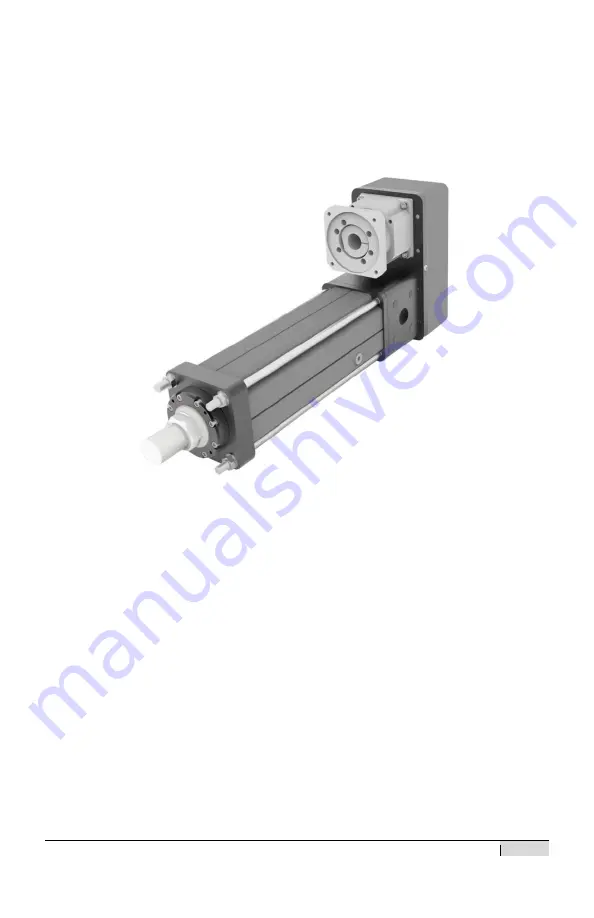
Page 7: ...test flexibility in application The base actuator includes a high performance satellite roller screw assembly pre loaded angular contact bearings an epoxy powder coated aluminum housing stainless steel tie rods internal anti rotation mechanism a sealed output rod and a keyed input shaft for attachment to a drive system A typical base FTX Series actuator is shown below Figure 3 Base FTX Actuator ...

Page 8: ...zes a high performance synchronous belt drive system and the inline motor mounting configuration uses a zero backlash coupling to transmit power from the motor to the input shaft of the actuator Typically a drive ratio of 1 1 is used but a 2 1 reduction ratio is also available as standard on the parallel motor mounting configuration FTX series actuators will also mate up with a wide variety of sta...

Page 9: ... product misalignment of the FTX Series actuator with respect to the load the actuator is being used to move is of great concern Any misalignment will decrease the life of the components within the actuator and also may create problems within the application associated with misalignment Therefore every effort should be made to minimize misalignment as much as is possible Excessive side load on the...

Page 10: ...26 17 10 2 3 Motor Installation 1 Remove parallel drive cover screws washers cover and gasket The screws are hand tightened from the factory for shipment 2 Attach motor or gearbox to motor plate using supplied mounting screws washers and gasket ...

Page 11: ...rbox output shaft and actuator input shaft Refer to belt tensioning procedure for the approximate distance between the pulley and motor plate Torque the Taper Lock screws to specification The Taper Lock bushings can be used with or without a key Figure 5 Motor and Pulley with Taper Lock Bushing ...

Page 12: ...ay have to be reversed to attain proper pulley distance In some instances the bushing and pulley may have to be installed before the motor is attached to the motor plate to allow clearance for tightening the bushing Torque the bushing using the large hex and refer to the torque specification for bushing torque Figure 6 Motor Pulley with keyless Style Bushing ...

Page 13: ...fer to section 3 3 for belt installation belt tension and cover assembly 6 For inline motor mounting an elastomer jaw coupling is used The coupling must be fitted flush to the end of the motor shaft Figure 7 Inline Motor Mounting Figure 8 Coupling Alignment ...

Page 14: ... assembled into inline housing assembly This is a blind assembly and may require reposition of motor coupling to match actuator coupling Do not force installation or use motor mount screws to join pieces If any resistance is felt reposition motor coupling to aid alignment A light film of oil will aid in the assembly process Figure 10 Inline Mount Final Assembly ...

Page 15: ...ues Its operating range is 40 degrees C to 177 degrees C 40 degrees F to 350 degrees F Periodic inspection and renewal of the bearing and roller screw grease is recommended Re greasing and maintenance schedules are largely based upon customer applications Contact the factory for general recommendations on re greasing schedules Follow the procedure in section 3 6 for renewing the lubrication Upon i...

Page 16: ...ir specific application The case features integrated sight glasses and sight tubing to ensure a proper oil fill level depending upon the orientation of the actuator Slight foaming of the oil in operation is normal and is a result of the initial coating of grease from the bearings Figure 11a Horizontal Oil Fill Sight Glasses Figure 11b Vertical Oil Fill Sight Tube and Fill Ports For lubrication of ...

Page 17: ... in correlation with stroke Fill the Actuator with the Main Rod Retracted ONLY Approximate Horizontal Oil Fill Level Actuator L qt FTX095 0150 0 36 0 38 FTX095 0300 0 57 0 60 FTX095 0600 1 00 1 05 FTX095 0900 1 42 1 50 FTX095 Oil Qty Per 25mm of Stroke 0 035 0 037 Approximate Horizontal Oil Fill Level Actuator L qt FTX125 0150 0 57 0 60 FTX125 0300 0 87 0 92 FTX125 0600 1 50 1 58 FTX125 0900 2 12 ...

Page 18: ...c plug ports are provided for fill and drain Proper oil quantity will vary with the stroke of the actuator as well as the motion profile Correct fill level should be decided by where the most work is done by the roller screw nut The nut should be submerged in oil or allowed to dip back into the standing oil in a cycle The tables below are an approximation for half oil fill This should be used as a...

Page 19: ...Level Actuator L qt FTX125 0150 0 57 0 60 FTX125 0300 1 44 1 52 FTX125 0600 3 17 3 35 FTX125 0900 4 90 5 18 FTX125 Oil Qty Per 25mm of Stroke 0 144 0 153 Approximate Rod End Up Level Actuator L qt FTX095 0150 0 12 0 12 FTX095 0300 0 67 0 70 FTX095 0600 1 77 1 86 FTX1095 0900 2 86 3 02 FTX095 Oil Qty Per 25mm of Stroke 0 091 0 096 Approximate Rod End Up Level Actuator L qt FTX125 0150 0 30 0 31 FTX...

Page 20: ... 68 4 95 FTX P215 0600 9 83 10 39 FTX P215 0900 14 98 15 83 FTX P215 Oil Qty Per 25mm of Stroke 0 429 0 453 Vertical Oil Fill Ports and Sight Tube Approximate Rod End Up Level Actuator L qt FTX P215 0150 1 75 1 84 FTX P215 0300 4 32 4 56 FTX P215 0600 9 47 10 00 FTX P215 0900 14 62 15 44 FTX P215 Oil Qty Per 25mm of Stroke 0 429 0 453 ...

Page 21: ...C PN71855 5 26 17 21 Vertical Oil Fill Dimensions Vertical Oil Fill Dimensions Actuator Nut Length A Bumper Height B FTX095 110 1mm 4 33 in 13 3mm 0 53 in FTX125 128 1mm 5 04 in 14 6mm 0 58 in FTX P215 199 2mm 7 84 in 24 8mm 0 98 in ...

Page 22: ...to move tooling Oil would only need to be filled up to the nut where the majority of the work is being performed by the roller screw The vertical oil fill table shows the bumper and nut height with each actuator In the example the oil level needs only to be above the nut level in the last 20mm With the bumper height being 24mm add in the additional over travel of the actuator of 25mm plus the dist...

Page 23: ...ese actuators However there is a limit to the amount of torque they can withstand and every effort should be made to resist installation torque applied when tightening a nut or coupling on the output rod There are wrench flats provided on every standard output rod to aid in resisting installation torque Figure 12 Anti Rotate Mechanism During installation do not apply more than the following values...

Page 24: ...late of the actuator The input shaft is sealed using a spring loaded shaft seal that is contained within the back plate of the actuator These seals are lubricated on initial assembly with grease however the front gland seal should have a small amount of mineral oil applied to it periodically depending on amount of actuator use or storage to keep the seal operating smoothly and to prolong life Figu...

Page 25: ...1 75 inch ID 70635 Seal BT 1 75 inch ID 70755 Bearing Linear Sleeve 10076 O Ring 137 Buna N70 FTX125 63032 Wiper AY 2 25 inch ID 63033 Seal BT 2 25 inch ID 63034 Bearing Linear Sleeve 62679 O Ring 233 Buna N70 FTX P215 69308 Wiper AY 4 25 inch ID 69309 Seal BT 4 25 inch ID 69307 Bearing Linear Sleeve 64084 O Ring 248 Buna N70 ...

Page 26: ... effectiveness and life The belt and pulley system should be inspected periodically for excessive wear and proper tensioning Do not remove the belt cover while the actuator is operating Always remove power from the attached motor before removing the belt cover to service any component of the drive train i e belts pulleys bushings inline couplings gears etc Failure to do so can result in damage to ...

Page 27: ...he image below shows the proper distance to fix the pulley from the motor plate See torque chart for bushing screw torque values Figure 15 Belt Distance from Motor Plate 2 Separate Idler assembly from T bolt and remove the Tension Adjustment Screw Install the T bolt into the end of the slot Belt centered on pulley width ...

Page 28: ...ht FTX Series Rev C PN71855 5 26 17 28 3 The belt can now be placed onto the pulleys 4 With the belt in place the idler assembly can now be placed back over the T bolt T Bolt Tension Adjustment Screw Idler Assembly ...

Page 29: ... tension Measure belt tension by using span deflection method OR Sonic Meter Belt Frequency using a Sonic Meter is the preferred method Actuator Size Installation Deflection mm in Deflection Force Min N lbf Deflection Force Max N lbf Frequency Min Hz Frequency Max Hz FTX095 3 1 0 122 27 0 6 07 28 6 6 43 137 143 FTX125 3 1 0 122 38 2 8 61 40 6 9 14 118 124 FTX215 3 8 0 149 66 7 15 00 70 7 15 90 102...

Page 30: ...w measure the belt span length t as shown in the picture above With one pulley free to rotate use a spring scale to apply a perpendicular force to the center of the belt width at the mid point of the belt span The appropriate amount of force for each belt is shown in the belt tension table Measure the deflection of the belt at the mid point While applying the correct force the belt deflection shou...

Page 31: ...ut 6 Verify belt tension is at appropriate level after applying specified torque Readjust if necessary 7 Install Motor Plate Sealing Screw and sealing washer Torque to spec 8 Reinstall the gasket and rear cover with the Cover to Motor Mounting Plate screws Torque the screws to the appropriate value specified in the fastener torque section ...

Page 32: ...mature failure Do not run the roller screw into the end of its stroke in either extension or retraction as this will severely damage the actuator and or application 3 5 End of Stroke Cushions Every FTX Series actuator is equipped with impact bumpers which are designed to protect the actuator from accidental over extension or retraction This is a fail safe only and should not be used as a limit to ...

Page 33: ... designs may differ from these procedures and any questions should be verified with Exlar before reassembling and reinstalling the actuator into your machine or application Drive train disassembly 1 Remove the actuator assembly from the application or machine by removing power from the motor disconnecting main rod coupling and actuator mounting bolts or fasteners If the servo motor gearbox is moun...

Page 34: ...the pulley bushing off the pulley using the back out threads provided in the pulley or bushing Then remove the motor pulley and bushing and remove the motor from the motor plate Figure 19 Parallel Motor Mount Disassembly 5 Remove motor plate to actuator mounting screws and washers The motor plate can now be removed from the actuator ...

Page 35: ...ove motor plate screws and motor plate Figure 20 Inline Mount Motor Plate Removal 8 Remove nuts and tie rods or in some models screws holding the adapter plate to the inline housing Remove adapter plate Some actuators have multiple adapter plates to align and mount the motor correctly 9 Remove the inline housing and gaskets Figure 21 Inline Housing Removal ...

Page 36: ...17 36 10 Loosen the actuator coupling mounting screw and remove coupling Note For installation the actuator coupling is mounted flush with the end of the input shaft Remove the inline housing adapter plate 11 Installation is the reverse of removal ...

Page 37: ...the rear stop 25mm The grease zerk will now be accessible Follow the chart below for the correct amount of grease to use Cycle the unit after several cc s of grease to distribute Figure 22 Grease Port Location Apply grease into zerk through port in case cycle actuator to distribute grease Actuator Size Initial Grease Fill cc Additional cc Grease per 25mm Stroke FTX095 5 25 0 26 FTX125 7 88 1 00 FT...

Page 38: ...commodate any one of the many standard servo motors or planetary gearboxes offered from a wide variety of manufactures 4 3 Limit Switches FTX actuators equipped for adjustable externally mounted limit switches Exlar offers magnetic proximity switches that are triggered by a target magnet that is located in the anti rotate mechanisms inside of the actuator housing The location of the four target ma...

Page 39: ...ly Open NPN Not Supplied Not Supplied L5 Normally Closed NPN Normally Closed NPN Not Supplied L6 Normally Open NPN Normally Closed NPN Normally Closed NPN Switch Type Exlar Part Number Supplier Part Number Normally Closed Switch PNP 43404 Turck P N BIM UNT RP6X Normally Open Switch PNP 43403 Turck P N BIM UNT AP6X Normally Closed Switch NPN 67635 Turck P N BIM UNT RN6X Normally Open Switch NPN 676...

Page 40: ...ems associated with the amplifier and motor 5 0 Specifications 5 1 Life Calculations The expected life of the roller screw in a FTX actuator is expressed as the linear travel distance that 90 of the screws are expected to meet or exceed before experiencing metal fatigue This is not a guarantee For accurate lifetime calculations of a roller screw in a linear application cubic mean load should be us...

Page 41: ...alog for ratings and formulas regarding the linear speed of the FTX actuators 5 3 Load and Speed Ratings Each FTX actuator model has an associated maximum force rating The maximum force rating is a value that should never be exceeded either by or applied to the actuator Consult the Exlar catalog for maximum force ratings DO NOT exceed maximum force ratings of the FTX actuators Doing so can and wil...

Page 42: ... to motor remove belt cover and inspect belt or inline coupling Replace if necessary Motor does not operate Motor electrical problem Consult motor manufacturer Output rod has excessive rotation or rotates but does not extend Anti rotate failure Replace anti rotate mechanism Excessive motor current to operate actuator An internal mechanism binding application binding roller screw failure Operation ...

Page 43: ...ease discuss the return with Exlar Technical Support prior to requesting an RGA number to see if it is possible to resolve the issue prior to return If it is determined that an RGA number is required please do so by completing an online RGA request form located at http exlar com return authorization request International Repairs Closely follow instructions provided by the Exlar Returned Goods Admi...

Page 44: ...CS SS 63303 4 60 44 242 Clevis Eye to Adapter Plate FTC and FTG Option Screw M12x1 75 x 30mm SHCS SS 63303 4 60 44 242 Inline Housing Screws Screw M10x1 5 x SHCS SS 4 52 38 242 Inline Adapter Plate Screws Screw M8x1 25 x 20mm SHCS SS 38215 4 26 19 228 242 Actuator Shaft to Motor Shaft Coupling Size 60 Coupling M6 Screw 2 15 11 133 N A Size 150 Coupling M10 Screw 2 35 25 310 N A Trunnion Mounting S...

Page 45: ...HCS SS 38709 4 68 50 242 Inline Housing Screws Screw M12x1 75 x SHCS Magni Coat 4 87 64 242 Inline Adapter Plate Screws Screw M8x1 25 x 35mm SHCS SS 30001 4 26 19 228 242 Actuator Shaft to Motor Shaft Coupling Size 150 Coupling M8 Screw 2 35 26 310 N A Size 300 Coupling M10 Screw 2 70 52 620 N A Trunnion Mounting Screws Screw M12x1 75 x 30mm SHCS SS 70890 8 60 44 242 Grease Access Plug Plug Hex So...

Page 46: ... Screw M16x2 0 x 140mm SHCS 69284 12 108 80 242 Motor Plate Sealing Screw Screw M12x1 75 x 16mm BHCS SS 69058 1 14 10 120 242 Clevis Eye to Adapter Plate Screw M24x3 0 x 60mm SHCS SS 69321 4 203 150 242 Inline Housing Nut Nut M20x2 5 Hex Magni Coat 69120 4 136 100 N A Motor Plate to Adapter Plate Screw M12x1 75 x 30mm SHCS SS 63303 8 87 64 774 242 Actuator Shaft to Motor Shaft Coupling Size 450 Co...

Page 47: ... 800 N A Idler Assembly Hex Nut Nut 3 4 10 UNC Hex 10991 1 271 200 N A Drive Cover to Motor Plate Screw M16x2 0 x 140mm SHCS 69284 12 108 80 242 Motor Plate Sealing Screw Screw M12x1 75 x 16mm BHCS SS 69058 1 14 10 120 242 Inline Housing Nut Nut M20x2 5 Hex Magni Coat 69120 4 136 100 N A Motor Plate to Adapter Plate Screw M12x1 75 x 30mm SHCS SS 63303 8 87 64 774 242 Actuator Shaft to Motor Shaft ...

Page 48: ... m M2 5x0 45 7 lb in 0 8 N m 1 4 20 62 lb in 7 N m M4 x0 7 19 lb in 2 1 N m 5 16 18 9 lb ft 12 N m M5x0 8 29 lb in 3 3 N m 3 8 16 16 lb ft 22 N m M6x1 0 62 lb in 7 N m 7 16 14 26 lb ft 35 N m M8x1 25 9 lb ft 12 N m 1 2 13 41 lb ft 56 N m M10x1 5 16 lb ft 22 N m 9 16 12 50 lb ft 68 N m M12x1 75 26 lb ft 35 N m 5 8 11 69 lb ft 94 N m M14x2 0 50 lb ft 68 N m 11 16 12 95 lb ft 129 N m M16x2 0 69 lb ft...

Reviews: