background image

4. Pre-installation Instructions 

Page 

6

 of 

28


4. Pre-installation Instructions 


Unpacking


  Carefully remove the packaging from each product  and check for damage. 

Immediately report any damage to EXHEAT Industrial Ltd (please keep this IOM and 
the additional certification booklet for future reference). 

  Remove the heater using the handle provided and place on the ground, remove any 

optional extras from the box and discard the packaging responsibly. 

  Visually inspect the heater casing for damage. Again, report any damage to EXHEAT 

Industrial Ltd straight away. 

  Carefully lift the heater onto a bench or workspace then gently lay the heater on its 

side to gain access to the enclosures underneath. 


Before carrying out the following inspections, ensure no attempt is made to 

connect a power supply to the heater. The following instructions may only be 

completed while the heater is completely isolated from a source of power. 

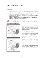
Pre-Installation Inspection 

  Each heater  is manufactured to the highest 

standard with great care and quality materials.  
All the goods are thoroughly inspected and 
tested before leaving the manufacturing plant, 
and they must be handled with care during 
storage and installation.  

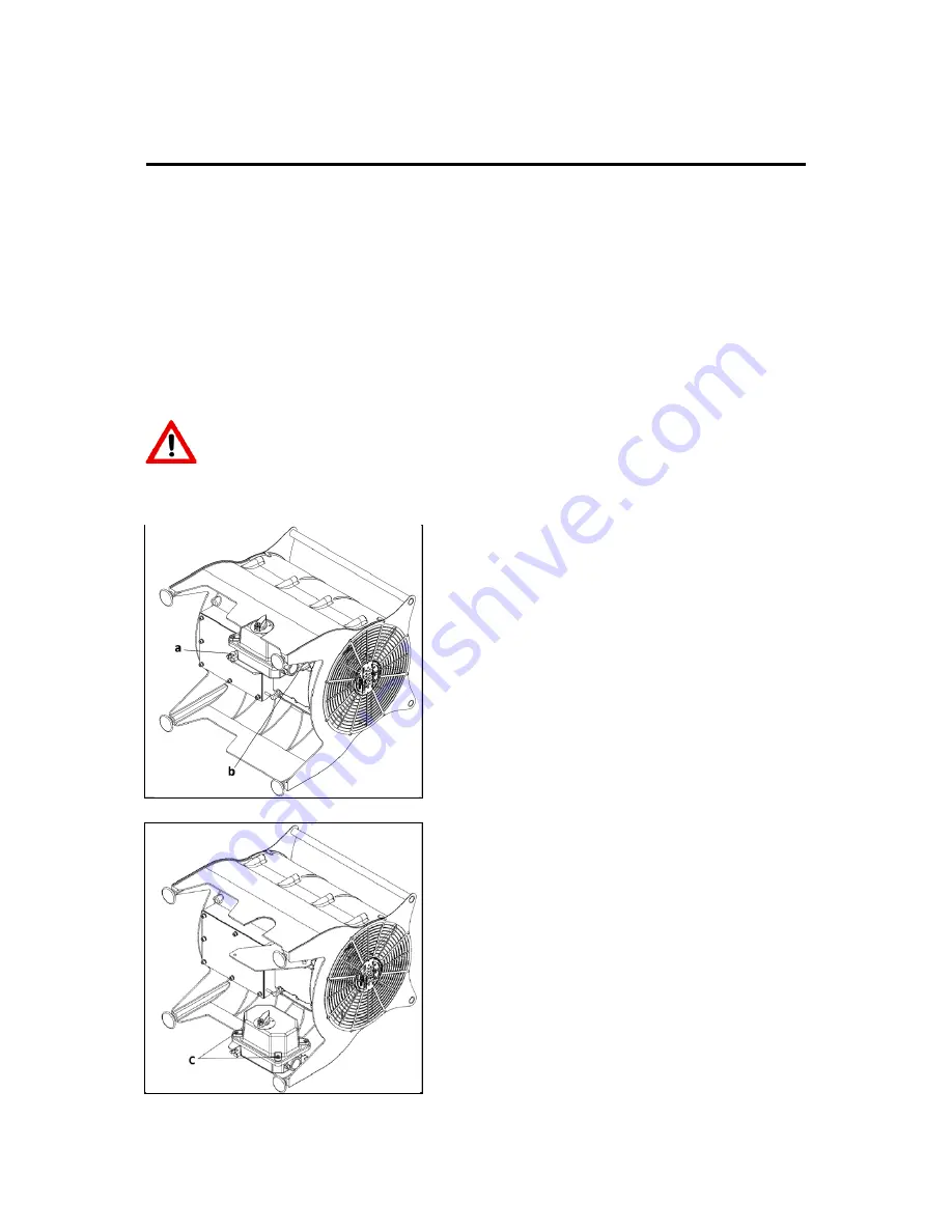
  Carefully lay the fan heater on its side with the 

side entry into the casing facing up. 

  If fitted with an optional local isolator, carefully 

remove fixing (a.) and loosen fixing (b.) and 
slide the enclosure housing towards you. See 
Fig 4.1. Rotate so as not to apply any 
additional stress on the cable and set down. 
See Fig 4.2. 

  Remove the four fasteners (c.) and carefully 

place the lid to one side so as not to damage 
the flamepath. 

  Carefully remove the seven fasteners (d.) on 

the stainless steel enclosure and remove the 
lid. See Fig 4.3. 

  If not fitted with an optional local isolator, 

remove the seven fasteners (d.) on the 
stainless steel enclosure and remove the lid. 


Fig 4.1 

Fig 4.2 

Summary of Contents for MFH T3

Page 1: ...Installation Operation Maintenance Instructions Manual MFH Portable Air Warmer...

Page 2: ...19 11 General Arrangement Drawings 21 12 Wiring Diagrams 22 13 Routine Maintenance Inspection Record 25 EXHEAT Industrial can provide versions of this manual in German French Italian Spanish Portugue...

Page 3: ...k IP25 6NG Tel 44 0 1953 886 210 Fax 44 0 1953 883 853 Email sales exheat industrial com Website www exheat industrial com Technical Support EXHEAT Industrial Ltd Threxton House Threxton Road Industri...

Page 4: ...o ITS 17 ATEX 101743 X Ex db eb IIB H2 T3 T4 Gb Ex tb IIIC T200 C T135 C Db Certificate No IECEx ITS 17 0012 X The Heater Range MFH T4 MFH T3 Voltage Duty Voltage Duty 110 2 5kW 220 240 380 415 5 5kW...

Page 5: ...e gaskets Heating Elements Stainless Steel sheathed tubular element with fully brazed individual stainless steel fins Motor Housing Epoxy Coated Aluminium suitable for both onshore and offshore applic...

Page 6: ...g EXHEAT Industrial Ltd CAUTION The following preservation instructions must be adhered to failure to do so could result in the equipment warranty being invalidated Store the equipment at between 0 C...

Page 7: ...may only be completed while the heater is completely isolated from a source of power Pre Installation Inspection Each heater is manufactured to the highest standard with great care and quality materia...

Page 8: ...connecting any supply cables ensure that the incoming power supply conforms to the specified voltage on the products nameplate at a nominal variance of 5 of the specified voltage Compliance with thes...

Page 9: ...ual and on the drawings certification supplied also be aware of any additional warning that may be present on the product on any warning labels At no time is the ambient temperature to be allowed to r...

Page 10: ...cket to prevent snagging Electrical Supply Connection without Optional Local Isolator fitted Refer to the wiring diagram in Section 12 Cable entry to the main terminal enclosure is via 1 off M20 Certi...

Page 11: ...AT Industrial Ltd can facilitate this No alterations are permitted to the factory installed wiring The cable glands installed to the MFH heater should be such that they do not decrease the IIB H2 rati...

Page 12: ...be protected by a suitable device wired to shut down the product if the thermostat fails to earth Suitable devices include a residual current device RCD this is the preferred method and should be used...

Page 13: ...nsit damage The heaters must be handled with care and stored in clean and dry conditions as per section 3 All prevailing rules regulations and bylaws in force at the time and place of installation mus...

Page 14: ...alled and the power is energised no adjustments to the heater are allowed The MFH portable fan heater is designed to operate in ambient temperature range of 40 C to 40 C and the user must ensure that...

Page 15: ...ual The following preventative maintenance should be carried out at the intervals shown below for any replacement parts please contact EXHEAT Industrial Ltd Compliance with these maintenance instructi...

Page 16: ...l enclosure cover during wet or humid conditions as this could lead to a reduction in insulation resistance of the thermostat Ensure the 5mm grub screws that affix the impeller to the motor are tight...

Page 17: ...ntenance before energizing Check for component failure in line with section 5 if there is component failure or low insulation resistance contact EXHEAT Industrial Ltd for further advice Only EXHEAT In...

Page 18: ...must not be placed within 0 5m of any wall structure or other obstruction to the air inlet Impeller side or outlet The heater must not be covered in any way whilst in operation or until fully cooled a...

Page 19: ...er from the power supply Access the Ex e enclosure and ensure that phase numbering is correct Swap the cables between two of the incoming phases L1 and L2 only There is no heat Isolate the heater from...

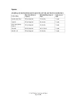
Page 20: ...tween Failures Estimated Replacement Time Spares Lead Time Replacement Feet When Required 10 minutes 1 week Impeller When Required 45 minutes 1 week RTD Temperature Sensor When Required 60 minutes 1 w...

Page 21: ...ment Page 20 of 28 10 COSHH Statement Health and Safety Information There are no hazardous or toxic substances applied with this order as defined in COSHH control of substances hazardous to health reg...

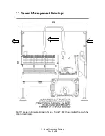
Page 22: ...11 General Arrangement Drawings Page 21 of 28 11 General Arrangement Drawings Fig 11 1 General arrangement drawing for both T3 and T4 MFH heaters when fitted with the optional local isolator...

Page 23: ...Page 22 of 28 Fig 11 2 General arrangement drawing for both T3 and T4 MFH heaters when not fitted with the optional local isolator 11 General Arrangement Drawings FAN ROTATION...

Page 24: ...g Diagrams Page 23 of 28 12 Wiring Diagrams Fig 12 1 Single Phase element wiring Diagram Fig 12 2 Single Phase Ex e enclosure terminal wiring Diagram Connections to be made in accordance section 5 of...

Page 25: ...12 Wiring Diagrams Page 24 of 28 Fig 12 3 Three Phase element wiring Diagram Fig 12 4 Three Phase Ex e enclosure terminal wiring Diagram Connections to be made in accordance section 5 of this IOM...

Page 26: ...Page 25 of 28 Fig 12 5 12 6 Wiring diagrams for single phase and three phase MFH heaters fitted with the optional local isolator 12 Wiring Diagrams...

Page 27: ...asing and impeller blades with a damp cloth 06 Check that there is no dirt debris loose items or moisture within the terminal enclosure 07 Check that all electrical connections are undamaged and tight...

Page 28: ...ion Record Page 27 of 28 www exheat industrial com Copyright EXHEAT Industrial Ltd Fifth Edition March 2018 Author J Brown MFH IOM_English Refer to EXHEAT Industrial Ltd website for latest edition www...

Reviews: