Introduction
QualityAssurer 805
5
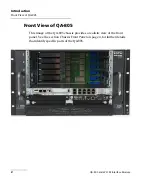
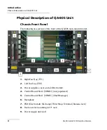
Physical Description of QA-805 Unit
10.
Power supply unit/slot 2
11.
Power supply unit/slot 3
12.
Power supply unit/slot 4
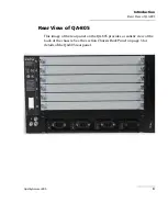
Chassis Back Panel
The following is a picture of the back of the QA-805 chassis.
13.
Shelf Ground Terminals
14.
Individual Power Switch for each power supply
15.
Individual AC Inlet for each power supply
16.
ESD Wrist Strap Terminal (Banana Jack)
17.
Power Bridge slot
18.
Shelf FRU (field replacement unit)
Summary of Contents for Quality Assurer QA-604
Page 1: ...User Guide QA 805 and W2 CM Interface Module...
Page 8: ......
Page 30: ......
Page 44: ......
Page 52: ......


