background image

Introducing the FIP-500 Fiber Inspection Scope

Fiber Inspection Scope

7

Battery Status Icon Description

Battery Status Icon Description

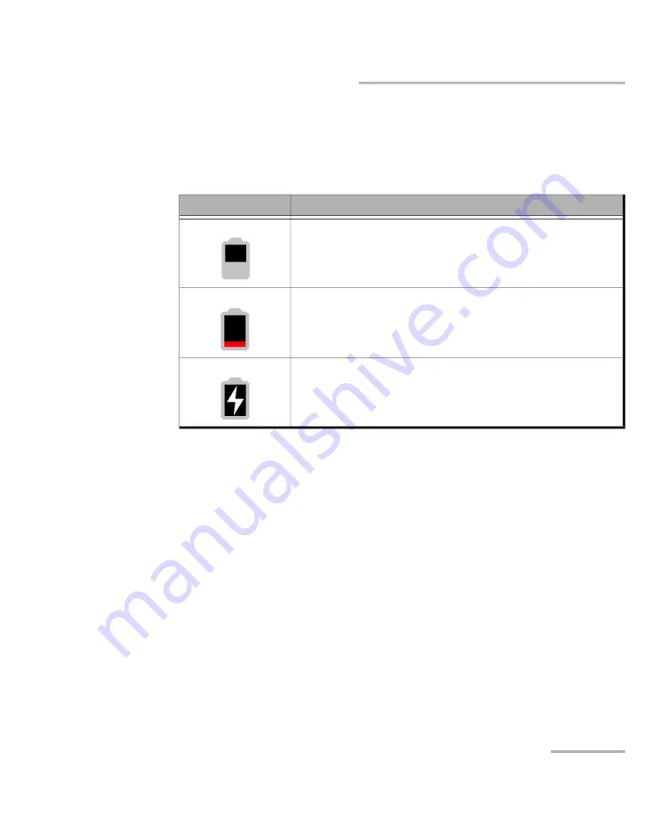
The battery status icon is shown in the upper right corner of the title bar. It 
complements the information provided by the unit’s LED.

Icon

Meaning

The portion of the icon that appears in white in the title 

bar (in gray here) reflects the current battery level. 

A red icon indicates that the battery level is running 

low and that you should connect the unit to a power 

outlet.

A flash symbol indicates that the unit is connected to 

an external power source.

Summary of Contents for FIP-500

Page 1: ...User Guide Fiber Inspection Scope FIP 500 www EXFO com...

Page 2: ...rights of EXFO EXFO s Commerce And Government Entities CAGE code under the North Atlantic Treaty Organization NATO is 0L8C3 The information contained in this publication is subject to change without n...

Page 3: ...our Unit 17 Turning off Your Unit 18 Configuring Your Unit at First Startup 19 Understanding the Inspection Screen 21 Changing Your Unit s SmarTip 22 Changing Your Unit s Optical Head 26 Cleaning and...

Page 4: ...Recommendations 79 Recharging the Battery 81 Replacing the Battery 84 Upgrading Software 91 Recycling and Disposal 92 8 Troubleshooting 93 Solving Common Problems 93 Restoring Your Unit to Normal Oper...

Page 5: ...nerates uses and can radiate radio frequency energy and if not installed and used in accordance with the user documentation may cause harmful interference to radio communications Operation of this equ...

Page 6: ...his device complies with Innovation Sciences and Economic Development Canada license exempt RSS standards Operation is subject to the following two conditions 1 This device may not cause harmful inter...

Page 7: ...n can be achieved if the device can be kept as far as possible from the user s body RF Function and Frequency Range Your unit is designed to operate in the Bluetooth and WLAN 2 4 GHz bands and at 13 5...

Page 8: ...all EU member states and EFTA countries Local Restrictions on 802 11a 802 11b 802 11d 802 11g 802 11n and 802 11ac Radio Usage Due to the fact that the frequencies used by 802 11a 802 11b 802 11d 802...

Page 9: ...h European Directive 2014 53 EU The full text of the EU declaration of conformity is available at the following Internet address www exfo com en resources legal documentation Note Information such as...

Page 10: ......

Page 11: ...e the examination of patchcord connectors and also hard to reach connectors on the back of patch panels and bulkhead adapters Main Features Ergonomic design 2 4 inch capacitive touchscreen directly on...

Page 12: ...ensure optimum protection when you do not use the unit or during transportation cover the optical head with the provided protective cap Side view Power on off button Eyelet for protective cap Dual fun...

Page 13: ...Introducing the FIP 500 Fiber Inspection Scope Fiber Inspection Scope 3 Main Features Back view Touchscreen...

Page 14: ...Several configurations are available for the fully automated and wireless FIP 500 Fiber Inspection Scope Configuration Description SF To inspect single fiber connectors MF To inspect both single and m...

Page 15: ...ent power to charge the battery Blue The battery is fully charged Blue blinking slow blinking The battery is charging Blue blinking fast blinking The battery charge has been interrupted possibly becau...

Page 16: ...aning Blue The unit is ready and operational The flashlight feature is disabled Blue blinking The capture process is in progress Green steady for 5 seconds The analysis found no defects or scratches e...

Page 17: ...of the title bar It complements the information provided by the unit s LED Icon Meaning The portion of the icon that appears in white in the title bar in gray here reflects the current battery level...

Page 18: ...ts to charge the battery The actual results will vary with each vehicle You could also use a certified USB power bank portable charger to charge your unit Indoor and outdoor use One lithium ion Li ion...

Page 19: ...ation which if not avoided could result in death or serious injury Do not proceed unless you understand and meet the required conditions CAUTION Indicates a potentially hazardous situation which if no...

Page 20: ......

Page 21: ...dures namely for operation and maintenance other than those specified herein may result in hazardous radiation exposure or impair the protection provided by this unit WARNING If the equipment is used...

Page 22: ...nd and meet the required conditions before using your product IMPORTANT When you see the following symbol on your unit it indicates that the unit is equipped with a laser source or that it can be used...

Page 23: ...or more of the following symbols may also appear on your unit Symbol Meaning Direct current Alternating current The unit is equipped with an earth ground terminal The unit is equipped with a protecti...

Page 24: ...utdoors To avoid electrical shock do not operate the unit if any part of the outer surface covers panels etc is damaged Only authorized personnel should carry out adjustments maintenance or repair of...

Page 25: ...unit Equipment Ratings Temperature Operation unit powered by battery 10 C to 40 C 14 F to 104 F unit connected to AC power with USB power adapter 0 C to 40 C 32 F to 104 F a Storage unit short term st...

Page 26: ...battery can either charge more slowly than usual or not charge at all depending on the internal temperature of your unit b Short term storage corresponds to the storage of the unit for a maximum of 48...

Page 27: ...FO license agreement and set the date and time see the section about the first startup for more information Note The settings you modify at startup can be modified later if necessary To turn on the un...

Page 28: ...restart routine the next time you use it You should perform a shutdown if you do not intend to use your unit for several hours After a shutdown the unit will start in the inspection screen Note Shoul...

Page 29: ...in this documentation Unless otherwise specified the information applies both to the Android and iOS based smart devices Note Both on your unit and in the EXFO Exchange application the period is used...

Page 30: ...a Wi Fi network that will allow you to retrieve the software updates You can proceed as follows 6a Install the EXFO Exchange application on your smart device see Installing the EXFO Exchange Applicati...

Page 31: ...tapping anywhere in the non active area gray background of the image or directly on the image of the fiber when you view a specific fiber Title bar indicating the status information of elements such...

Page 32: ...r and multi fiber connectors you may find useful to leave the most frequently used SmarTip attached to its optical head and change the complete SmarTip optical head assembly instead For more informati...

Page 33: ...s SmarTip To change your unit s SmarTip 1 If necessary remove the protective cap from the unit 2 Turn the SmarTip retaining nut counterclockwise until the pins are aligned with the widest part of the...

Page 34: ...ntation of the SmarTip either key up or key down when applicable suits your test setup In all cases ensure that the widest part of the anchoring slots is aligned with the pins 5 Slide the SmarTip towa...

Page 35: ...r Inspection Scope 25 Changing Your Unit s SmarTip 6 Turn the SmarTip retaining nut clockwise until the pins are aligned with the narrowest part of the anchoring slots to secure the SmarTip in place T...

Page 36: ...eed to switch from one type of inspection to the other There is no need to disassemble the SmarTip from your unit before changing the optical head To change the optical head 1 Slightly turn the optica...

Page 37: ...Getting Started with Your Unit Fiber Inspection Scope 27 Changing Your Unit s Optical Head 2 Gently pull on the optical head to remove it...

Page 38: ...Started with Your Unit 28 FIP 500 Changing Your Unit s Optical Head 3 Align the arrow on the new optical head with the arrow on your unit and then gently put the optical head back in place Alignment...

Page 39: ...it in place the pins on the unit will be aligned with the narrowest part of the anchoring slots on the optical head 5 Configure the settings as required according to the type of optical head and Smar...

Page 40: ...ently wipe the fiber end with a lint free swab dipped in optical grade liquid cleaner 2b Use a dry swab to dry the connector completely 2c Visually inspect the fiber end to ensure its cleanliness IMPO...

Page 41: ...equate contact If your connector features a screw sleeve tighten the connector enough to firmly maintain the fiber in place Do not overtighten as this will damage the fiber and the port Note If your f...

Page 42: ...ction For more information on the effects of temperature on battery charging see Power Sources on page 8 IMPORTANT For optimum performance of your unit Ensure that it remains within the recommended op...

Page 43: ...lf to better fit your work environment or preferences You may also want to reduce the display brightness to save battery power the higher the brightness level the higher the power consumption The brig...

Page 44: ...kly set the brightness to the minimum or the maximum value The new brightness value is taken into account immediately Adjusting the Date and Time The date and time are expressed in international forma...

Page 45: ...Scroll down to the Unit settings section 3 Tap Date and time 4 Tap the entry corresponding to the element that you want to modify 5 Modify the settings according to your needs and then tap to return t...

Page 46: ...default the duration after which the unit goes into sleep mode is fifteen minutes but you can select another value The value that you set is kept in memory even when you turn the unit off To configur...

Page 47: ...our Unit Fiber Inspection Scope 37 Configuring the Sleep Mode 3 Tap Sleep 4 Select the desired number of minutes and then tap to return to the Date and time screen The new value is taken into account...

Page 48: ...ttings that you have customized such as the delay before the unit switches to sleep mode to their default values This operation does not affect the current date and time and does not delete any stored...

Page 49: ...4 Tap Factory settings 5 Tap RESET to confirm your choice and start the operation When the operation is complete the unit will restart 6 Configure the date and time and accept the license agreement as...

Page 50: ......

Page 51: ...ectors or fiber stub transceivers such as the MPO MTP TM OptiTip and Q ODC By default the 1x12 fiber layout is selected but you can select another fiber layout that will correspond to the connector yo...

Page 52: ...and interface types 1 From the inspection screen tap SF single fiber connector type currently selected or the numbers corresponding to the fiber layout multi fiber type selected 2 In the Connector ty...

Page 53: ...the Connector and Interface Types 3 If you work with multi fiber connectors proceed as follows 3a Select the fiber layout corresponding to the connector you want to inspect 3b Select the key orientati...

Page 54: ...for single fiber connectors is independent of the one that you select for multi fiber connectors This means that you can select different fiber types if necessary to better suit your test environment...

Page 55: ...th 200 500 MHz km Fiber channel designation M6 Fiber jacket is orange or slate Multimode OM2 Modal bandwidth 500 MHz km Fiber channel designation M5 Fiber jacket is orange Multimode OM3 Modal bandwidt...

Page 56: ...ection screen tap the fiber type 2 In the Fiber type screen select the desired type of fiber If you are not sure whether your setup uses singlemode or multimode fiber you can have a look at the color...

Page 57: ...sure that the proper SmarTip is installed on your unit see Changing Your Unit s SmarTip on page 22 3 Select the desired connector type including the fiber layout and key orientation multi fiber inspec...

Page 58: ...debris that could be located outside the perimeter of the fibers themselves From this overview you can access the detailed capture of any of the inspected fibers that are part of the connector and vic...

Page 59: ...image of the fiber small circle or the desired fiber number To return to the overview From the detailed capture view tap the icon Image of a fiber Fiber number Global pass fail status of the connector...

Page 60: ...ladding and the adhesive are represented with circles The color of the circles shows the status of the analysis zone green pass red fail blue no analysis performed The overlay applied on a specific fi...

Page 61: ...tion LED that can serve as a flashlight to help you locate the connectors This is particularly useful when the environment in which you must perform the inspection is dark To turn on or turn off the f...

Page 62: ......

Page 63: ...Android and iOS based smart devices Installing the EXFO Exchange Application on Your Smart Device Before you start working if you intend to retrieve the software updates for your unit you will need to...

Page 64: ...r unit but if you have disabled it you must enable it before trying to connect to a smart device see Enabling or Disabling the Wireless Communication on page 59 On your FIP 500 unit the status of the...

Page 65: ...the Bluetooth communication on your unit see Enabling or Disabling the Wireless Communication on page 59 2 If it is not already done install the EXFO Exchange application on your smart device see Ins...

Page 66: ...ation establishes the communication automatically When the connection is successful the icon remains displayed in the title bar of your FIP 500 unit The unit identified with its serial number is added...

Page 67: ...oth Technology To close the connection with a smart device from your unit 1 From the main menu tap Settings 2 From the Wireless section tap Disconnect mobile app 3 When the application prompts you con...

Page 68: ...ce Via the Bluetooth Technology To close the connection with release an FIP 500 from a smart device 1 From the Test units screen tap the line corresponding to your FIP 500 unit 2 Tap FORGET THIS TEST...

Page 69: ...t and the EXFO update services to retrieve software updates are accomplished using a connection to a wireless network By default the Bluetooth communication is enabled on your unit but the Wi Fi is no...

Page 70: ...Wireless Communication To enable or disable the wireless communication from your unit 1 From the main menu tap Settings 2 From the Wireless section use the Wi Fi or Bluetooth toggle to enable or disa...

Page 71: ...s already been established between your unit and a smart device see Establishing or Closing a Connection With a Smart Device Via the Bluetooth Technology on page 54 2 On the smart device open the EXFO...

Page 72: ...Communication on page 59 Before being able to connect your unit to a Wi Fi network you must first configure the desired networks with the EXFO Exchange application Your unit supports IPv4 wireless rou...

Page 73: ...the name of the wireless networks in the EXFO Exchange application The table below shows the possibilities Icon Meaning No Wi Fi icon visible in the title bar The Wi Fi communication is disabled The...

Page 74: ...s the last network used are kept in memory for future use even when you turn your unit off To configure a wireless network 1 Ensure that a Bluetooth connection has already been established between you...

Page 75: ...e 65 Working With a Wireless Network 4 From the Test units screen tap the line corresponding to your FIP 500 unit 5 Tap Wi Fi 6 Tap the item corresponding to the wireless network that you want to conf...

Page 76: ...unication automatically Connecting to a Wireless Network From Your Unit When you start a new work session with your unit it will automatically connect to the last network used unless this network is n...

Page 77: ...a Keep the unit out of direct sunlight Avoid high humidity or significant temperature fluctuations Avoid unnecessary shocks and vibrations If any liquids are spilled on or into the unit turn off the p...

Page 78: ...leaning solution especially manufactured by camera lens manufacturers can be used safely Reagent grade isopropyl alcohol as well as deionized water can also be used safely Gently remove oil fingerprin...

Page 79: ...clean lenses 1 If necessary turn off your unit and remove the protective cap 2 Turn the SmarTip retaining nut counterclockwise until the pins are aligned with the widest part of the SmarTip anchoring...

Page 80: ...Maintenance 70 FIP 500 Cleaning Lenses 3 Pull on the SmarTip to remove it 4 Clean the lens that is located at the end of the optical head Optical head Multi fiber optical head Lens...

Page 81: ...Maintenance Fiber Inspection Scope 71 Cleaning Lenses Lens Single fiber optical head...

Page 82: ...lightly turn the optical head retaining nut counterclockwise to release it from your unit the pins on the unit will be aligned with the widest part of the anchoring slots on the optical head Widest pa...

Page 83: ...Maintenance Fiber Inspection Scope 73 Cleaning Lenses 6 Gently pull on the optical head to remove it...

Page 84: ...art of the lens that is located at the end of the optical head Note You will need a swab measuring at least 15 cm 6 inches to clean the inner part of the single fiber optical head lens Multi fiber opt...

Page 85: ...Maintenance Fiber Inspection Scope 75 Cleaning Lenses 8 Using a lint free swab clean the focus lens Focus lens...

Page 86: ...Maintenance 76 FIP 500 Cleaning Lenses 9 Align the arrow on the optical head with the arrow on your unit and then gently put the optical head back in place Alignment arrows...

Page 87: ...nspection Scope 77 Cleaning Lenses 10 Slightly turn the optical head retaining nut clockwise to secure it in place the pins on the unit will be aligned with the narrowest part of the anchoring slots o...

Page 88: ...igned with the narrowest part of the anchoring slots to secure the SmarTip in place Your unit is now ready to use Cleaning the Touchscreen Clean the touchscreen with a soft non abrasive cloth such as...

Page 89: ...approved batteries may result in the batteries expanding or igniting that is catching fire WARNING Risk of explosion if battery is replaced by an incorrect type Dispose of used batteries according to...

Page 90: ...l Standard IEC 62133 Covers secondary cells and batteries containing alkaline or other non acid electrolytes In some countries when required EXFO approved batteries have been certified and are marked...

Page 91: ...g low and that you should connect the unit to a power outlet For more information see Battery Status Icon Description on page 7 The unit also indicates the charge status with the LED on its side see L...

Page 92: ...ore slowly than usual or not charge at all depending on the internal temperature of your unit Do not leave a battery discharged for several days After 300 cycles approximately 18 months of use you may...

Page 93: ...nit to such a USB port with the USB cable the unit will still consume battery power If the unit is off when you connect it to the USB port of a computer its battery could charge but slowly Note If you...

Page 94: ...an only replace it with batteries of the same type and model The use of other batteries may damage your unit and compromise your safety You can purchase new batteries from EXFO Battery replacement sho...

Page 95: ...animation will be displayed on the screen 2 If applicable disconnect the USB cable 3 Position the unit so that its side panel with the on off button rests on a flat surface such as a table 4 On the ca...

Page 96: ...Maintenance 86 FIP 500 Replacing the Battery 5 Hold the cover by its sides and pull it up to remove it...

Page 97: ...Maintenance Fiber Inspection Scope 87 Replacing the Battery 6 Gently pull on the battery connector to disconnect it from its socket Battery Battery wires Battery connector...

Page 98: ...7 Pull the battery up to remove it Socket for battery connection...

Page 99: ...y so that its wires and connector are located on the same side as the socket in your unit s case The battery connector should be facing down 9 Place the new battery in the bottom of the case 10 Connec...

Page 100: ...panel until alignment is correct 12 Using a 2 5 mm hex socket screwdriver turn the screws 6 clockwise until they are tightened This will secure the side panel into place IMPORTANT If the battery LED t...

Page 101: ...e Your unit allows you to check for updates download these updates and install them directly Note Your unit must have access to an Internet connection via Wi Fi to be able to download updates and inst...

Page 102: ...nstall it your unit will restart automatically at the end to complete the process Recycling and Disposal For complete recycling disposal information visit the EXFO Web site at www exfo com recycle Thi...

Page 103: ...it with a new one see Replacing the Battery on page 84 The system has encountered a problem Press the on off button for at least ten seconds to force a hardware reset on the unit a Some files essentia...

Page 104: ...FO Ambient temperature is too high or too low In this case the battery LED is blue and blinks fast Make sure that the temperature in the location where you recharge the battery is within the specifica...

Page 105: ...ion problem with the network Ensure that the Wi Fi connection is enabled on your unit see Enabling or Disabling the Wireless Communication on page 59 In the case of a secured network ensure that the p...

Page 106: ...rt device or a laptop that you will use to give your unit access a wireless network When it is done configure this Wi Fi hotspot as you would with any Wi Fi network see Configuring a Wireless Network...

Page 107: ...he screen 2 Connect your unit to a power outlet using the provided USB power adapter This will ensure that your unit remains powered on during the whole recovery operation 3 Press and hold the trigger...

Page 108: ...t the EXFO license agreement set the date and time and read safety instructions as you did when you first received your unit see Configuring Your Unit at First Startup on page 19 10 If desired perform...

Page 109: ...ocumentation You can access the user guide at all times from your smart device Note The user guide is also available from the EXFO Web site www exfo com for download in PDF format To access the user g...

Page 110: ...Troubleshooting 100 FIP 500 Accessing the Online Documentation 3 Tap Support 4 Use a smart device to scan the QR code and access the user guide...

Page 111: ...d information about technical support and for a list of other worldwide locations visit the EXFO Web site at www exfo com If you have comments or suggestions about this user documentation you can send...

Page 112: ...tion such as the serial number of your unit as well as the approximative date and time when the captures were taken close at hand Your unit will need access to a Wi Fi connection to be able to share c...

Page 113: ...r Inspection Scope 103 Sharing Information With the Technical Support Group To share information with the technical support group 1 From the main menu tap Settings 2 Scroll down to the Unit settings s...

Page 114: ...the Share captures with EXFO link is not available dimmed it means that all the captures have been transferred to the support server already 5 When the application prompts you read the information and...

Page 115: ...mportant information such as the model of your unit the serial number as well as the software and hardware versions directly from your unit You can also find the contact information if you ever need t...

Page 116: ...Troubleshooting 106 FIP 500 Viewing System Information 3 Tap About The information you want to view is displayed on the screen...

Page 117: ...Troubleshooting Fiber Inspection Scope 107 Viewing System Information To retrieve the contact information 1 From the main menu tap Settings 2 Scroll down to the Unit settings section 3 Tap Support...

Page 118: ...mage can occur from improper handling The following steps are recommended to minimize the possibility of damage Pack the unit in its original packing material when shipping Avoid high humidity or larg...

Page 119: ...ring the warranty period and found to meet all published specifications EXFO will charge standard calibration fees THIS WARRANTY IS IN LIEU OF ALL OTHER WARRANTIES EXPRESSED IMPLIED OR STATUTORY INCLU...

Page 120: ...product is sold by an unauthorized intermediary A product is designed and destined for a particular market and sold on a second market A product is resold despite being reported lost or stolen When pr...

Page 121: ...ny time without incurring obligation to make any changes whatsoever on units purchased Accessories including but not limited to fuses pilot lamps batteries and universal interfaces EUI used with EXFO...

Page 122: ...itions under which it was observed 5 Return the equipment prepaid to the address given to you by support personnel Be sure to write the RMA number on the shipping slip EXFO will refuse and return any...

Page 123: ...trument services exfo service centers EXFO Headquarters Service Center 400 Godin Avenue Quebec Quebec G1M 2K2 CANADA 1 866 683 0155 USA and Canada Tel 1 418 683 5498 Fax 1 418 683 9224 support exfo co...

Page 124: ......

Page 125: ...le 50 LED 5 Bluetooth closing connection 54 connectivity 1 establishing connection 54 55 frequency band data vii viii status 54 56 boot first 19 brightness adjusting 33 icon 34 button on off 2 5 17 82...

Page 126: ...avorite networks 62 64 fiber ends cleaning 30 fiber ends inspecting 47 first startup 19 flashlight 51 frequency Bluetooth and Wi Fi vii viii front panel cleaning 67 G green circle 50 H help online 99...

Page 127: ...62 64 product identification label 101 main features 1 specifications 9 purchasing new batteries 80 R recharging the battery 81 83 recovery operation 96 red circle 50 LED 5 94 regional and language s...

Page 128: ...8 features 1 location on unit 3 transportation requirements 67 108 turning on off unit 17 18 Wi Fi or Bluetooth 59 U understanding inspection screen 21 unit first configuration 19 repairing 14 restori...

Page 129: ...y K K K K K 0HFKDQLFDO VXE DVVHPEO D D K K K K K K 1RWH 7KLV WDEOH LV SUHSDUHG LQ DFFRUGDQFH ZLWK WKH SURYLVLRQV RI 6 7 d 2 QGLFDWHV WKDW VDLG KD DUGRXV VXEVWDQFH FRQWDLQHG LQ DOO RI WKH KRPRJHQHRXV P...

Page 130: ...0 5 1 5 48 5 0 176 W d y K y K D...

Page 131: ...com P N 2 0 0 1 CORPORATE HEADQUARTERS 400 Godin Avenue Quebec Quebec G1M 2K2 CANADA Tel 1 418 683 0211 Fax 1 418 683 2170 TOLL FREE USA and Canada 1 800 663 3936 2021 EXFO Inc All rights reserved Pr...

Reviews: