background image

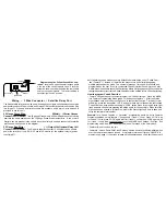
To Activate the Trunk Release*:  

   Press & Hold the lower right

transmitter TRUNK button for 2 seconds

The trunk will be released after 2 seconds, and the Status Light will flash twice.  If the

doors are also programmed to unlock with Trunk Release, the parking lights will flash twice
and stay on for 30 seconds, and the horn will chirp 2 times if it is connected.

Remote  Trunk  Release

Multiple  Vehicle  Operation

The unit’s transmitter can operate two different vehicles equipped with this system.  The
slide switch on the side of the transmitter is utilized for this- one car can be operated in
switch position “A” and the second car in switch position “B”.

Transmitters must be coded for multiple vehicle operation- an easy procedure which is
explained on pages 17-19.

* Connection of the trunk release may require additional parts, and may not be included in a standard
installation.

Caution: When such a wire is located, be sure to also test that it is non-rheostated:
While metering the wire, operate the dash light dimmer control. The correct wire will
show no change in voltage when the dimmer is operated.  Some vehicles have a parking-
light relay which is triggered by a Negative signal from the headlight switch. In these ve-
hicles, the White wire must be connected after the relay, usually at the Fuse/Junction Block.
Do NOT connect  the White wire directly to the vehicle’s headlights. An external relay is
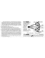
required.   Vehicles having a split
parking light system must be diode-
isolated, requiring the use of two

IN4006 diodes:

123456

123456

123456

123456

123456

123456

123456

123456

123456

123456

123456

123456

123456

123456

123456

123456

123456

123456

123456

123456

123456

123456

123456

123456

123456

123456

123456

123

123

123

123

123

123

123

123

123

123

123

123

123

123

123

123

123

123

123

123

123

Right Side Circuit

White Wire

Light

Switch

Left Side Circuit


Parking Lights

Diode Isolation Of Split
Parking Light Systems


Two IN4006 Diodes.

Control
Module

  The function of the Orange wire is to provide a 500mA Nega-

tive auxiliary output which may be used to operate a starter motor "Anti-Grind" relay, which
prevents accidental starter grind should the key be turned while the remote starter is in
operation.  Additionally, the Orange wire also provides the vehicle immobilizing feature for
the Anti-Carjacking operation.  Connection instructions are included with optional starter
interrupt socket and relay.

20-Gauge Orange  Wire:

( - ) Anti-Grind Output

Connection If Desired.

Summary of Contents for Excalibur RS-22

Page 1: ...Circumstances Should This Warranty Or The Product Covered By It Be Construed As A Guarantee Or Insurance Policy Against Loss The Company neither assumes nor authorizes any person or organization to m...

Page 2: ...Overview 4 Remote Locking Unlocking the Doors 5 Remote Starting the Engine 5 7 Remote Panic 7 Remote Trunk Release 8 Multiple Vehicle Operation 8 The Receiver Unit 9 Programmable Features 9 17 Program...

Page 3: ...switch will have 3 wires 3 A Positive pulse system uses factory relays or a control unit a Reversing system does not 5 Wire Reversing Polarity Systems Congratulations for choosing your Remote Starter...

Page 4: ...Positive system Basic Transmitter Functions The unit includes two 4 button remote transmitters a switch on the side can operate a second system The control buttons functions are shown here and how the...

Page 5: ...Lock the Vehicle s Doors Press Release the upper left transmitter LOCK button Locking Unlocking the Doors To Unlock the Vehicle s Doors Press Release the upper right transmitter UNLOCK button The park...

Page 6: ...or locking the vehicle s doors Programmable feature 12 changes the single unlock pulse to be a double unlock pulse 22 Gauge Blue Wire 500mA Unlock Output Connection If Desired This harness which plugs...

Page 7: ...anic To Activate Panic Press Hold either transmitter LOCK or UNLOCK button for 3 seconds The horn will sound the parking lights will flash and the doors will lock or unlock de pending on the transmitt...

Page 8: ...t relay which is triggered by a Negative signal from the headlight switch In these ve hicles the White wire must be connected after the relay usually at the Fuse Junction Block Do NOT connect the Whit...

Page 9: ...the rear body harness or firewall connector 18 Gauge White Wire Parking Light Output Connection Recommended The unit has a total of 14 programmable features most of these are operational features som...

Page 10: ...ccessory Power circuit this output can be used to spike the door pin switch wire which will turn off the Retained Accessory Power circuit To arm a factory alarm after remote start engine run stops con...

Page 11: ...ward the 12 pin secondary harness see page 21 and the markings on the control module 3 Adjust the tach signal by starting the engine and turning the right adjustment screw on the control module slowly...

Page 12: ...stallation after all other wiring connections are made Smart Start sensing is more commonly used for its ease of installation The unit as received has Smart Start selected Smart Start reads the vehicl...

Page 13: ...e Black Yellow wire is the engine detect wire The unit uti lizes two different methods of monitoring the vehicle during the remote starting pro Feature 1 Coded Override may be used another programmabl...

Page 14: ...onds after the key was turned On Anti Carjacking fully en gages sounding the horn and flashing the parking lights pressing the Valet Switch will no longer cancel the feature Instead the ignition key m...

Page 15: ...rough 9 are chosen and programmed by the user Even if a customized Coded Override is used only one Valet Switch press is needed to cancel Anti Carjacking before it fully engages at 60 seconds after th...

Page 16: ...may be used for engines which do not start on the first remote start attempt Programming choices are 5 second LOCK the default setting 75 second UNLOCK 1 25 second START and 1 5 second TRUNK page 26...

Page 17: ...harness is the best source for these wires and the Starter Ignition 1 and Accessory wiring connections Feature 12 is Doorlock Output Options The default setting is the most common Single pulse for bot...

Page 18: ...obstructed on the vehicle s glass such as the windshield behind the rearview mirror Make sure the glass surface is clean and free of dust grease or debris Peel the backing off of the adhesive tape 1 T...

Page 19: ...oid sparks and do not smoke while working near the vehicle s battery Always protect wires routed through the firewall from sharp metal edges and hot parts of the engine Always fuse positive wires at t...

Page 20: ...OUTPUT BLACK YELLOW ENGINE DETECT INPUT RED BLACK BRAKE INPUT YELLOW GREEN OEM DISARM OUTPUT GRAY TRUNK RELEASE OUTPUT BLUE HOOD INPUT ORANGE ANTI GRIND OUTPUT PINK BLACK START ACTIVATION INPUT BROWN...

Reviews: