EWT VIVALDI DE LUXE VVLD20 Information Manual Download Page 32

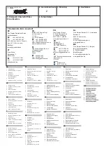
2.  Garantiezeitraum 3. Modell(e)

4. Kaufdatum

5. Stempel & Unterschrift des

Einzelhändlers

7. Kontakt-Tel.-Nr. & - Anschrift

1. Garantiekarte

2

GR

1. Κάρτα εγγύησης

εγγύησης (έτη)

6. Σφάλµα/Ελάττωµα

KZ

SK

1. Zárucný list
2. Zárucné obdobie (v rokoch)
3. Model(y)
4. Dátum kúpy
5. Pecat & Podpis obchodníka
6. Porucha/závada
7. Kontaktujte císlo & adresu

LT

1. Garantijos kortele
2. Garantijos laikotarpis (metais)
3. Modelis (modeliai)
4. Pirkimo data
5. Prekybininko antspaudas ir

parašas

6. Gedimas / defektas
7. Numeris ir adresas kontaktams

EE

1. Garantiikaart
2. Garantiiaeg (aastates)
3. Mudel(id)
4. Ostukuupäev
5. Kaupluse tempel & allkiri
6. Viga/defekt
7. Kontaktnumber & aadress

HU

1. Garancialevél
2. Garancia idotartama 

(években)

3. Modell(ek)
4. Vásárlás idopontja
5. Eladó bélyegzoje és aláírása
6. Hiba/Hiány megnevezése
7. Értesítési telefonszám és cím

HR

1. Jamstvena kartica
2. Jamstveni period (u godinama)
3. Model(i)
4. Datum kupnje
5. Pecat i potpis dobavljaca
6. Kvar/defekt
7. Broj i adresa za kontakt

FI

1. Takuukortti
2. Takuuaika (vuosina)
3. Malli(t)
4. Ostopäivämäärä
5. Myyntiliikkeen leima ja

allekirjoitus

6. Vika/vaurio
7. Yhteysnumero  ja  osoite

PL

1. Karta gwarancyjna
2. Okres gwarancji (w latach)
3. Model(e)
4. Data zakupu
5. Pieczec i podpis sprzedawcy
6. Usterka
7. Telefon i adres kontaktowy

CZ

1. Záruční list
2. Záruční doba (roky)
3. Model(y)
4. Datum zakoupení
5. Razítko a podpis prodejce
6. Porucha/chyba
7. Kontaktní číslo a adresa

LV

1. Garantijas talons
2. Garantijas periods (gadi)
3. Modelis(li)
4. Legades datums
5. Mazumtirgotaja zimogs un

paraksts

6. Bojajums/defekts
7. Kontakttalrunis un adrese

SI

1

. Garancijski list

2. Obdobje veljavnosti

garancije (v letih)

3. Model(i)
4. Datum nakupa
5. Žig in podpis prodajalca
6. Pomanjkljivost/okvara
7. Kontaktna številka in naslov

PT

1. Cartão de Garantia
2. Período de Garantia (em  anos)
3. Modelo(s)
4. Data de Compra
5. Carimbo e Assinatura do

retalhista

6. Falha/Defeito
7. Número de Contacto e Morada

NL

1. Garantiebewijs
2. Garantieperiode (in  jaren)
3. Model(len)
4. Aankoopdatum
5. Stempel & handtekening

winkelier

6. Storingen & gebreken
7. Telefoonnummer  &  adres

DK

1. Garantikort
2. Garantiperiode  (i  år)
3. Model(ler)
4. Købsdato
5. Detailhandlers  stempel  &

underskrift

6. Fejl/defekt
7. Kontaktnummer  &  -adresse

SE

1. Garantikort
2. Garantitid  (i  år)
3. Modell(er)
4. Inköpsdag
5. Återförsäljarens  stämpel  och

underskrift

6. Fel
7. Telefonnummer  och  adress  för

kontakt

NO

1. Garantikort
2. Garantiperiode  (i  år)
3. Modell(er)
4. Kjøpsdato
5. Selgers stempel og signatur
6. Feil/defekt
7. Kontaktnummer og adresse

DE

1. Garantiekarte
2. Garantiezeitraum (in  Jahre)
3. Modell(e)
4. Kaufdatum
5. Stempel & Unterschrift

des Einzelhändlers

6. Fehler/Defekt
7. Kontakt-Tel.-Nr. & - Anschrift

UK

1. Warranty  Card
2. Guarantee  Period  (in Years)
3. Model(s)
4. Date  of  Purchase
5. Stamp & Signature of retailer
6. Fault/Defect
7. Contact Number & Address

FR

1. Bon de garantie
2. Période de garantie (en  années)
3. Modèle(s)
4. Date d’achat
5. Cachet et signature du vendeur
6. Anomalie/Défaut
7. Nom et adresse du contact

IT

1. Scheda di garanzia
2. Periodo di garanzia (in anni)
3. Modello(i)
4. Data di acquisto
5. Timbro e firma del rivenditore
6. Guasto/difetto
7. Indirizzo e numero di contatto

ES

1. Tarjeta  de  garantía
2. Período de garantía (en  años)
3. Modelo(s)
4. Fecha de adquisición
5. Sello y firma del distribuidor
6. Avería/Defecto
7. Número y dirección de contacto
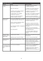
6. Fehler/Defekt

AT

Firma Schurz
Merangasse 17
A-8010 Graz

+43 (316) 32 30 41

Fax:

+43 (316) 38 29 63

[email protected]

R

DE

Glen Dimplex Deutschland Gmbh
ewt-Kundendienst

 +49 1805 / 398 346

Fax.

 +49 1805 / 355 467

(14Ct./Min. aus dem dt. Festnetz,
max.42Ct./Min. aus dem
Mobilfunk)
[email protected]

NO

Dimplex AS,

NO - 7493 Trondheim,

Norway.

+(47) 73 95 94 00

Fax:

+(47) 73 95 90 90

CH

BLUEPOINT Service Sagl,

Via Cantonale 14,

C.P.  46,
CH - 6917 Barbengo

+(41) 091 980 49 72

Fax: +(41) 091 605 37 55

eMail: [email protected]

www.bluepoint-service.ch

FR

Glen Dimplex France

ZI Petite Montagne Sud

12 rue des Cévennes

91017 EVRY - LISSES

www.glendimplex-france.fr

NL

Glen Dimplex Benelux B.V. – Netherlands
Saturnus 8,
8448 CC Heerenveen,
Nederland.
E-mail: [email protected]
www.glendimplex.nl

BE

Glen Dimplex Benelux B.V. – Belgium
Burg. Maenhautstraat 64,
B- 9820 Merelbeke,
België/ Belgique
E-mail: [email protected]
www.glendimplex.be

LT

UAB “Senuku prekybos centras”

Pramones pr. 6,

LT-51500,
Kaunas.

(8~800) 111 19

(8~37)  21 21 46

PL

Glen Dimplex Polska Sp. z o.o.

ul. Strzeszynska 33,

60-479 Poznan,

Poland

061 8425 805

Fax: 061 8425 806

eMail: [email protected]

Bratsbergvegen 5,

eMail: [email protected]

Summary of Contents for VIVALDI DE LUXE VVLD20

Page 1: ...ty Standards EN60335 2 30 and the European Standard Electromagnetic Compatibility EMC EN55014 EN60555 2 and EN60555 3 These cover the essential requirements of EEC Directives 2006 95 EC and 2004 108 EC 08 51776 0 Issue 1 VIVALDI DE LUXE VVLD20 R ...

Page 2: ...DE 1 GB 7 FR 13 IT 19 ...

Page 3: ...Fig 4 Fig 4a Fig 2 Fig 3 Fig 1 ...

Page 4: ...Fig 5 Fig 5a Fig 5b Fig 6 Fig 7 Fig 8 ...

Page 5: ...Fig 10 Fig 11 Fig 12 Fig 13 Fig 14 Fig 9 ...

Page 6: ...Fig 15 Fig 16 Fig 17 ...

Page 7: ...erden soll EIGENTÜMER BENUTZER 7 Dieses Gerät ist nicht für Kinder oder Personen mit eingeschränkten körperlichen sensorischen oder geistigen Fähigkeiten oder ohne Erfahrung und Wissen geeignet es sei denn sie werden von einer für ihre Sicherheit verantwortlichen Person beaufsichtigt und bzgl des Gebrauchs des Geräts angeleitet Kinder müssen beaufsichtigt werden damit sie nicht mit dem Gerät spiel...

Page 8: ...esswertgebers auf gleicher Höhe mit der Griffschale in der Wanne ist Abb 5a Das Kabel darf nicht über der Scheibe auf dem Messwertgeber platziert werden Abb 5b Setzen Sie das Kabel 7 in den Schlitz in der Wand der Wanne damit es nicht zwischen dem Ausguss und der Wanne eingeklemmt wird Setzen Sie den Verneblerdüse wieder ein Drehen Sie die Stifte um 90 Grad um den Ausguss zu befestigen 8 Abb 6 Was...

Page 9: ... der Steckdose und warten Sie ungefähr 10 Minuten bis Sie das Gerät erneut anschließen Entfernen Sie vor dem erneuten Einschalten des Ofens Hindernisse die die Wärmeabfuhr blockieren Setzen Sie dann den normalen Betrieb fort Achtung Um Gefahren durch ein ungewolltes Zurücksetzen der thermischen Abschaltung zu vermeiden darf das Gerät nicht durch ein externes Schaltgerät wie eine Zeitschaltuhr betr...

Page 10: ...heraus 1 Auch wenn der Ausguss noch installiert ist sollte es möglich sein die Lampen zu sehen und zu prüfen ob eine 2 Lampe ausgetauscht werden muss Setzen Sie den Schalter A auf die Position AUS und trennen Sie den Ofen vom Netz 3 Lassen Sie die Lampen des Geräts 20 Minuten abkühlen bevor Sie diese entfernen 4 Entfernen Sie die Wanne wie im Kapitel Reinigung beschrieben 5 Entfernen Sie die kaput...

Page 11: ...dafrika ZA 200808702 Mexiko MX 2008011712 Korea KR 20080113235 Japan JP 2009529649 Brasilien BR P10708894 9 Indien IN 4122 KOLNP 2008 Neuseeland NZ 571900 Wanne Stellen Sie den Schalter A auf die Position AUS 1 0 Heben Sie das Brennstoffbett vorsichtig heraus und setzen es auf den Boden 2 Heben Sie den Wassertank nach oben und heraus 3 Trennen Sie den elektrischen Verbinder der sich rechts von der...

Page 12: ...ts Erhöhen Sie die Flamme indem Sie den Regler D langsam nach links drehen Siehe Abb 10 Reinigen Sie die Metallscheibe mit der mitgelieferten weichen Bürste Siehe Abb 14 Schrittweise Anleitung siehe Kapitel Wartung Führen Sie das Kabel zur Rückseite der Wanne und stellen Sie sicher dass es sich im seitlichen Schlitz befindet und an der Wanne austritt Vor dem erstmaligen Betrieb Der Ofen muss sich ...

Page 13: ...ot required for long periods 7 OWNER USER This appliance is not intended for use by children or persons with reduced physical sensory or mental capabilities or lack of experience and knowledge unless they have been given supervision or instruction concerning use of the appliance by a person responsible for their safety Children should be supervised to ensure that they do not play with the applianc...

Page 14: ...slot in the wall of the sump 8 Replace the Sump Nozzle and secure it by turning the two red tabs by 90 degrees Fig 6 Filling the Water Tank 9 Place Water Tank in sink and remove cap turn anti clockwise to open Fig 7 10 Fill Water Tank with decalcified tap water only This is necessary to prolong the life of the flame and smoke producing unit The water should be filtered through a conventional domes...

Page 15: ...ou may make 4 The fire will use less water if the flame effect is set to a lower level 5 Do not tilt or move the fire while there is water in the tank or sump 6 Make sure that the fire is on a level floor REMOTE CONTROL OPERATION On the control panel Switch A Fig 10 must be in the ON I position in order for the remote control to operate There are 3 buttons on the remote control Fig 12 To operate c...

Page 16: ...e used to clean the outlet grille of the fan heater Water tank 1 Remove water tank as described earlier put into sink and empty water 2 Using the supplied brush gently rub the inside surfaces of the cap paying particular attention to the rubber ring in the outer groove and the centre rubber seal 3 Put a small quantity of washing up liquid into the tank refit the cap and shake well rinse out until ...

Page 17: ...life it not be disposed of with household waste Please recycle where facilities exist Check with your Local Authority or retailer for recycling advice in your country PATENT PATENT APPLICATION Products within the Optimyst range are protected by one or more of the following patents and patent applications Great Britain GB 2402206 GB 2460259 GB 2460453 GB 2418014 GB 2465738 GB 2449925 GB 2465537 GB ...

Page 18: ...start up Increase level of flame by turning Control knob D to the left slowly Fig 10 Clean the Metal Disc with soft brush supplied Fig 14 See Maintenance for a step by step procedure Direct the wire to the back of the sump and make sure it sits into the side slot exiting the sump Before first operation please allow the fire place to warm up to room temperature Unpleasant smell when unit is used Di...

Page 19: ...pareil n est pas prévu pour être utilisé par des enfants ou des personnes dont les capacités physiques sensorielles ou mentales sont réduites ou qui sont dénuées d expérience ou de connaissance sauf si elles ont pu bénéficier par l intermédiaire d une personne responsable de leur sécurité d une surveillance ou d instructions préalables concernant l utilisation de l appareil Il convient de surveill...

Page 20: ... encoche moulée du collecteur Fig 5a Assurez vous que le câble n est pas placé au dessus du disque sur le bloc de transducteur Fig 5b Pour éviter 7 que le câble ne se coince entre la buse et le collecteur placez le dans la fente se trouvant dans la paroi du collecteur Remettez la buse du collecteur en place et fixez la en faisant pivoter les deux pattes rouges de 90 degrés Fig 6 8 Remplir le réser...

Page 21: ...areil de chauffage du socle de prise de courant et attendez environ 10 minutes avant de le rebrancher Avant de rallumer l appareil enlevez tous les obstacles pouvant restreindre la sortie d air chaud puis continuez à le faire fonctionner normalement Avertissement Afin d éviter les risques liés à un redémarrage accidentel du coupe circuit thermique cet appareil ne doit pas être alimenté via un disp...

Page 22: ...che de charbon et le réservoir d eau 1 Il doit être possible d observer les ampoules avec la buse en place et de voir laquelle a besoin d être changée 2 Mettez le bouton A en position OFF et débranchez la cheminée du secteur 3 Attendez 20 minutes pour que les ampoules se refroidissent avant de les enlever 4 Enlevez le collecteur selon les instructions de la section Nettoyage 5 Enlevez l ampoule dé...

Page 23: ...2008011712 Corée KR 20080113235 Japon JP 2009529649 Brésil BR P10708894 9 Inde IN 4122 KOLNP 2008 Nouvelle Zélande NZ 571900 Collecteur Mettez le bouton A sur OFF 1 0 Enlevez doucement la couche de charbon et posez la par terre avec précaution 2 Enlevez le réservoir d eau en le soulevant 3 Débranchez le connecteur électrique se trouvant du côté droit du collecteur Voir Fig 5 4 Dégagez les pattes d...

Page 24: ...au des flammes en tournant lentement le bouton de commande D à gauche Voir Fig 10 Nettoyez le disque en métal à l aide de la brosse douce fournie Voir Fig 14 Voir Entretien pour des instructions pas à pas Orientez le fil vers le dos du collecteur et assurez vous qu il s emboîte dans la fente à la sortie du collecteur Avant la première utilisation veuillez attendre que la cheminée atteigne la tempé...

Page 25: ...O UTENTE 7 Quest apparecchio non è progettato per l uso da parte di bambini o persone con capacità fisiche sensoriali o mentali ridotte o senza l esperienza e la conoscenza necessarie a meno che non vi siano la supervisione o istruzioni riguardo l uso dell apparecchio da una persona responsabile per la loro sicurezza I bambini dovrebbero essere sempre supervisionati per assicurarsi che non giochin...

Page 26: ...o tra l ugello e il serbatoio posizionatelo nell incavo nella parete del serbatoio Riposizionate l ugello del serbatoio ed assicuratelo girando di 90 gradi le due linguette rosse Fig 6 8 Riempire il serbatoio dell acqua Posizionate il serbatoio in un lavandino e rimuovete il tappo girate in senso antiorario per aprirlo Fig 7 9 Riempite il serbatoio dell acqua solo con 10 acqua di rubinetto decalci...

Page 27: ...to da un interruttore che viene spento e acceso regolarmente OTTENERE L EFFETTO FIAMMA DESIDERATO La manopola di controllo della fiamma D Fig 10 può essere ruotata in alto o in basso per dare un effetto più 1 realistico Generalmente le fiamme appaiono più realistiche quando la manopola è al minimo 2 Date un po di tempo al generatore di fiamma per reagire alle modifiche fatte sulla manopola di cont...

Page 28: ...endita lì sono contenuti i dati su come acquistare le lampade Inserite con attenzione i due pin della nuova lampada nei due fori del supporto Premetela saldamente sul posto 7 Vedete Fig 4 e 4a Riposizionate il pozzetto l ugello il serbatoio dell acqua e il supporto carburante 8 PULIZIA Avviso mettete sempre il tasto A in posizione OFF 0 Vedete Fig 10 e scollegatelo dall alimentazione prima di puli...

Page 29: ...US 2008028648 US 13 167 042 Russia RU2008140317 Europa EP 2029941 EP 2201301 EP 2315976 EP 1787063 EP07723217 1 EP11170434 2 EP 11170435 9 Cina CN 101883953 CN 200980128666 2 CN 101057105 CN 101438104 Australia AU 2009248743 AU 2007224634 Canada CA 2725214 CA 2579444 CA 2645939 Applicazione di brevetto internazionale WO 2006027272 Sud Africa ZA 200808702 Messico MX 2008011712 Corea KR 20080113235 ...

Page 30: ...rando lentamente verso sinistra la manopola di controllo D Vedete fig 10 Pulite il disco di metallo con la spazzola morbida fornita Vedete Fig 14 Vedete il capitolo Manutenzione per una procedura passo passo Dirigete il cavo sul retro del pozzetto e assicuratevi che stia nel incavo laterale che esce dal pozzetto stesso Prima del primo utilizzo lasciate che il caminetto si scaldi fino a temperatura...

Page 31: ... detaljer kan fås hos den forhandler hvor du har købt apparatet Der kan kun støttes ret på garantien ved forelæggelse af købskvittering og kun inden for garantiperioden Garantien bortfalder hvis apparatet er blevet beskadiget anvendt forkert eller i tilfælde af uautoriseret indgreb i apparatet SE Garanti För denna apparat gäller de för inköpslandet utgivna garantibestämmelserna På förfrågan kan de...

Page 32: ...rs stempel underskrift 6 Fejl defekt 7 Kontaktnummer adresse SE 1 Garantikort 2 Garantitid i år 3 Modell er 4 Inköpsdag 5 Återförsäljarens stämpel och underskrift 6 Fel 7 Telefonnummer och adress för kontakt NO 1 Garantikort 2 Garantiperiode i år 3 Modell er 4 Kjøpsdato 5 Selgers stempel og signatur 6 Feil defekt 7 Kontaktnummer og adresse DE 1 Garantiekarte 2 Garantiezeitraum in Jahre 3 Modell e ...

Reviews: