background image

Check Card Detection on the Embedded Web Page

16 (20)

6

Check Card Detection on the Embedded Web
Page

The Flexy extension cards require no software configuration. They are automatically detected
by the base unit when the device boots.

6.1

Connecting to the Embedded Web Server

Configure the network parameters to set the computer being used to reach the web interface on
the same IP range than the LAN of the eWON device.

Once both devices are in the same IP range, connect the PC to one of the LAN port of the
eWON device.

Open an Internet browser and access the homepage of the eWON device by typing the LAN IP
address in the URL field (the default address is

http://10.0.0.53

).

A dialog box will pop-up asking for credentials. Default ones are:

login: adm

password: adm

For security reasons, changing the default password

adm

is an absolute

requirement. To change it, from the menu bar, click on

Setup > Users

and double

click on the

adm

entry to edit and save its password.

6.2

Detected Cards Displayed in the System Page

Once connected to the embedded web pages of the eWON device, the homepage displays the
system status including detected extension cards.

To access in details the system status summary, click on

Diagnostic > Status > System Info >

System

.

FLB 3601 – 3 USB Ports Extension Card Installation Guide

IG-0024-00 EN 1.1

Summary of Contents for FLB 3601

Page 1: ...FLB 3601 3 USB Ports Extension Card INSTALLATION GUIDE IG 0024 00 EN 1 1 ENGLISH ...

Page 2: ...es and standards HMS Industrial Networks SA will under no circumstances assume liability or responsibility for any problems that may arise as a result from the use of undocumented features timing or functional side effects found outside the documented scope of this product The effects caused by any direct or indirect use of such aspects of the product are undefined and may include e g compatibilit...

Page 3: ...scription 7 4 1 Mechanical Layout and Interfaces 7 4 2 Extension Card Label 7 4 3 Front Panel LEDs 8 4 4 eWON Flexy Extension Cards Environmental Conditions 9 4 5 USB Specifications 9 4 6 Plug the FLB 3601 into the Base Unit 9 4 7 Power Requirements 13 5 Powering on the Base Unit with its Extension Cards 15 6 Check Card Detection on the Embedded Web Page 16 6 1 Connecting to the Embedded Web Serve...

Page 4: ...This page intentionally left blank ...

Page 5: ...ds For additional related documentation and file downloads please visit www ewon biz support 1 2 Document History Version Date Description 1 0 2016 07 05 First release 1 2 2018 08 03 Changed Template 1 3 Related Documents Document Author Document ID eWON Flexy eWON CTS IG 0014 00 eWON Flexy 205 eWON CTS IG 0028 00 1 4 Trademark Information eWON is a registered trademark of HMS Industrial Networks ...

Page 6: ...y base units to work The base units have their own Installation Guide which can be found in the Related Documents p 3 This guide also addresses shortly how the extension cards integrate the base units as well as some recommendations on how to mount them See Base Unit Slot Compatibility p 9 for more details FLB 3601 3 USB Ports Extension Card Installation Guide IG 0024 00 EN 1 1 ...

Page 7: ...des of an electronic printed circuit board Therefore it is packed in an antistatic ESD bag In order to avoid ESD damage the product must be handled with the necessary precaution including Grounded ESD protective work surface Personnel grounding 3 3 Applicable Directives Standards and Compliances TheFLB 3601 inserted in a base unit belongs to class A Information Technology Equipment ITE In a domest...

Page 8: ...product must accept any interference received including interference that may cause undesired operation 3 3 4 Certifications The FLB 3601 has been certified by authorized bodies UL Certificate of Compliance COC 20161219 E350576 CB certificate DK 53957 A1 UL These certificates can be downloaded as PDF files on the eWON Support web site www ewon biz support FLB 3601 3 USB Ports Extension Card Instal...

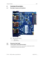
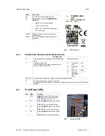
Page 9: ... 1 USB connectors 2 Back plane connector 4 2 Extension Card Label 4 2 1 Label Location and Included Information The identification label of the extension cards is placed on the solder side of the PCB The different parts of the label are described below FLB 3601 3 USB Ports Extension Card Installation Guide IG 0024 00 EN 1 1 ...

Page 10: ...rted A 2 first slots only B 2 last slots only X Any slots C Any slots Available for Flexy 205 only XXXX_00 The extension card type The suffix _00 is used for software options S The suffix might have an optional character It might also be blank or include S character Indicates compliance with the UL IEC EN 60950 standard 4 3 Front Panel LEDs Fig 3 Front panel LEDs Item Mark Function 1 STAT GREEN ON...

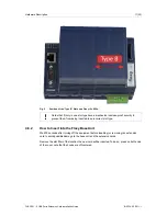
Page 11: ...Maximum current limit by USB port 500 mA max Earth gnd is limited to 500V due to USB connector 4 6 Plug the FLB 3601 into the Base Unit 4 6 1 Base Unit Slot Compatibility The FLB 3601 must be inserted in one of the Type B slots of the base unit The reference code of the extension cards includes a letter defining their compatibility FLB xxxx designate cards that fit into Type B slots In addition to...

Page 12: ...on of the Type B Slots on a Flexy 205 eWON Flexy 10x 20x The FLB 3601 must be inserted in the Type B slots which are the two slots on the far right of the Flexy 10x 20x FLB 3601 3 USB Ports Extension Card Installation Guide IG 0024 00 EN 1 1 ...

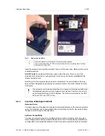
Page 13: ... 6 2 How to Insert into the Flexy Base Unit Wait 30 seconds after turning off the equipment before inserting or removing an extension card to avoid possible damage to the base unit and the extension cards Remove the slot filler of the location the new card will be inserted To do so press on both ends of the cover note that the hooks are off centered FLB 3601 3 USB Ports Extension Card Installation...

Page 14: ...rom left to right If an extension card is inadvertently forced in a wrong slot the base unit will detect the misplaced card and will not complete its boot process Therefore the unit will not be accessible through its LAN interface The slot error is returned by the USR LED red ON 1 sec OFF 0 5 sec 4 6 3 Insertion of Multiple FLB 3601 Detection Order The boot sequence of the base unit includes an au...

Page 15: ...he operation of the base unit itself nor does it alter its accepted extension cards 4 7 Power Requirements The Power Requirements concept doesn t apply to Flexy 205 and its inserted extension cards The internal power converter of the Flexy base units has been dimensioned to cover a broad range of different combinations of extension cards Users should make sure the total power demand of the extensi...

Page 16: ...re Description 14 20 The Installation Guide of the eWON Flexy Base Units also includes examples of practical power balance calculations FLB 3601 3 USB Ports Extension Card Installation Guide IG 0024 00 EN 1 1 ...

Page 17: ...ich the extension cards have been inserted and their type are detected during this process If the boot process completes normally the following LED status should be observed Base unit USR LED flashing green slowly Extension card None If the USR LED of the base unit is flashing red it might be because the extension card was improperly inserted for example in a wrong slot FLB 3601 3 USB Ports Extens...

Page 18: ...s the homepage of the eWON device by typing the LAN IP address in the URL field the default address is http 10 0 0 53 A dialog box will pop up asking for credentials Default ones are login adm password adm For security reasons changing the default password adm is an absolute requirement To change it from the menu bar click on Setup Users and double click on the adm entry to edit and save its passw...

Page 19: ... USB devices the firmware should increment from The USB functionality will start or stop accordingly to the UsbIpEnable parameter There is no need to restart the device to apply the new configuration UsbIpLogLevel UsbIpPwd UsbIpStartPort parameters are only used in advanced configuration or for debug purpose Modification of these parameters is not recommended 7 1 1 Default Values after Reset After...

Page 20: ...This page intentionally left blank ...

Page 21: ...rameter can be set to 2 in order to retrieve additional information in the logs The USB hub will only provide 500mA per port and will disconnect any device attempting to draw more For example some USB devices like self powered HDDs draw too much current In that case the LED will become RED then GREEN again and the real time log will show the repetitive failed sharing attempts Fig 9 Real time Log s...

Page 22: ...last page 2018 HMS Industrial Networks Box 4126 300 04 Halmstad Sweden info hms se IG 0024 00 EN 1 1 2018 08 03 9013 ...

Reviews: