background image

4-Line Interpolator

The 4-line interpolator uses a more sophisticated calculation based on the 4 neighboring
lines. By using suitable coefficients for the weight of each line in the resulting calculation,
we apply this interpolation to all fields. The final result is a permanently, slightly unfocused
picture. The advantage is a stable output signal with no jitter and no "pumping", but the
vertical bandwidth is even more reduced.

The interpolator is of course always disabled at 100% playback speed, because there is
no parity violation.

EVS uses the same techniques with the Super Slow Motion disk recorder, working with all
models of Super Motion cameras (150/180 Hz). The only difference between the
processing of Super Motion and normal scan (50/60 Hz) signals is that the interpolator is
always disabled at 33% playback speed, because the Super Motion signal does not cause
parity violation at this particular speed.

Whatever the choice, the resulting picture is thus always a compromise between stability
and resolution. With EVS systems, the operator always has the choice between any of
the 3 above described techniques: no interpolation, 2-line interpolation or 4-line
interpolation. Even if the operator chooses to use the interpolation, this process will be
automatically disabled when not necessary (100% playback for 50/60 Hz signal, 33% and
100% playback for 150/180 Hz signal).

Note

All professional VTRs use line interpolation in PlayVar mode to avoid vertical
jitters.
Default value is interpolator off for all configurations except SLSM
configurations in which 4-line interpolator mode is enabled.

24

4. Software Specifications

EVS Broadcast Equipment SA

Issue 12.02.A - December 2013

Summary of Contents for XT nano

Page 1: ...HARDWARE TECHNICAL REFERENCE MANUAL Version 12 02 December 2013 ...

Page 2: ......

Page 3: ...t hesitate to send improvement requests or report any error or inaccuracy on this user manual by e mail to doc evs com Regional Contacts The address and phone number of the EVS headquarters are usually mentioned in the Help About menu in the user interface You will find the full list of addresses and phone numbers of local offices either at the end of this user manual for manuals on hardware produ...

Page 4: ......

Page 5: ...onditions 9 4 SOFTWARE SPECIFICATIONS 10 4 1 Video Specifications 10 4 2 Audio Specifications 11 4 3 Video Codecs and Bitrates 12 4 3 1 Supported Codecs 12 4 3 2 Maximum Bitrates 14 4 3 3 Internal Bandwidth 15 4 3 4 Recording Capacities 18 4 4 Gigabit Ethernet Transfers 19 4 5 Video Interpolation 23 5 HARDWARE INSTALLATION AND CABLING 25 5 1 Rack Installation 25 5 2 Rear Panel Description 26 5 2 1...

Page 6: ...5 7 GPIO Connections 38 5 7 1 GP In Connections 38 5 7 2 GP Out Connections 40 6 BOARDS DESCRIPTION 42 6 1 Boards and Slots Configuration 42 6 2 V3X Video and Reference Boards 43 6 2 1 Description 43 6 2 2 COD Connectivity in SD and HD 46 6 2 3 COD Connectivity in 3D Dual Link 49 6 2 4 Channel Assignment 51 6 3 Audio Codec Board 52 6 4 H3X Board 53 6 5 RAID Controller Boards 55 6 5 1 RCTL Board on...

Page 7: ...cal Reference manual has not been subject to changed related to new features for release 12 02 The following changes are not related to new features Electric consumption data for power supplies See section Power Supply on page 8 Modified requirements See section Environmental Conditions on page 9 HARDWARE TECHNICAL REFERENCE MANUAL XTnano Server 12 02 What s New V ...

Page 8: ......

Page 9: ... motion replay servers from EVS Optimized for multiple applications such as ingestion of audio video files live feed recording live slow motion and super motion clipping and playlist playout control XTnano servers offer a flexible configuration They natively support a wide range of HD Intra codecs such as Mjpeg Avid DNxHD VC 3 Apple ProRes MPEG 2 intra Panasonic DVCPRO HD AVC Intra Class 100 as we...

Page 10: ...pean European Electromagnetic Compatibility EMC Part 3 Limits Section 3 limitation of voltage fluctuation and flicker in low voltage supply systems for equipment with rated current of 16 A EN 61000 4 3 European European Electromagnetic Compatibility EMC Part 4 Limits Section 3 Testing and measurement techniques Radiated radio Frequency electromagnetic field immunity test EN 61000 4 4 European Euro...

Page 11: ...pproved by the manufacturer for compliance could void the user s authority to operate the equipment This equipment generates uses and can radiate radio frequency energy and if not installed and used in accordance with the instructions may cause harmful interference to radio communications However there is no guarantee that interference will not occur in a particular installation If this equipment ...

Page 12: ...ffixed to indicate compliance with the following directives 89 336 EEC of 3 May 1989 on the approximation of the laws of the Members States to electromagnetic compatibility 73 23 EEC of 19 February 1973 on the harmonization of the laws of the Members States relating to electrical equipment designed for use within certain voltage limits 1999 5 EC of 9 March 1999 on radio equipment and telecommunica...

Page 13: ...Mount 4U Main Frame Weight 4U 19 inches chassis 30 kg 66 15 lb Dimensions The following drawings provide the various dimensions in mm of the XTnano server with a 4U chassis Front View Left View HARDWARE TECHNICAL REFERENCE MANUAL XTnano Server 12 02 3 Hardware Specifications 5 ...

Page 14: ...Right View Back View 6 3 Hardware Specifications EVS Broadcast Equipment SA Issue 12 02 A December 2013 ...

Page 15: ...lly be connected to your server to control it Nano Remote Control Panel Weight 3 4 kg 7 5 lb Keyboard Weight 0 4 kg 0 9 lb Tablet Weight 0 3 kg 0 66 lb Ref Wacom CTF 430 Bamboo One HARDWARE TECHNICAL REFERENCE MANUAL XTnano Server 12 02 3 Hardware Specifications 7 ...

Page 16: ...pe A EN 60950 1 2 5 Equipment which is intended for connection to the building power supply wiring via a non industrial plug and socket outlet or a non industrial appliance coupler or both Correct mains polarity must always be observed Do not use reversible power plugs with this equipment Class of equipment Class 1 equipment EN 60950 1 2 5 electric shock protection by basic insulation and protecti...

Page 17: ...ng requirements Forced air cooling air flow from right to left when looking the back panel of the EVS server Handling movement Designed for fixed use when in operation Storage and Transport Temperature 0 C to 70 C 32 F to 158 F Relative humidity 0 to 90 non condensing HARDWARE TECHNICAL REFERENCE MANUAL XTnano Server 12 02 3 Hardware Specifications 9 ...

Page 18: ...erface 10 bit 4 2 2 Serial ST 259 2008 Full frame synchronizer at input 10 bit 4 2 2 Serial ST 292 1 2011 Full frame synchronizer at input Number of Channels 4 or 6 channels reversible REC PLAY 4 or 6 channels reversible REC PLAY Monitoring Down converters 1 SD SDI per channel with OSD 1 HD SDI output per channel with OSD Reference Analog Black Burst Analog Black Burst and HD Tri Level Sync Graphi...

Page 19: ...08 ST 2020 3 2008 4 2 Audio Specifications Audio Analog and Digital Configurations The following optional audio configurations are available Configuration BNC AES EBU DA 15 Analog 16 input and 16 output 8 pairs 8 pairs AES EBU or Dolby E unbalanced on 16 BNC connectors 8 input and 8 output analog balanced channels on 4 DA 15 connectors Configuration DA 15 AES EBU DA 15 Analog 16 input and 16 outpu...

Page 20: ...es 4 3 1 Supported Codecs Codecs and Related License Codes The XTnano server supports natively the video codecs presented in the table below when the required license code is valid The XTnano server can be purchased with a single codec license Codec SD HD Code Protection IMX Code 11 Mjpeg SD Code 10 DVCPro 50 Code 9 Mjpeg Standard HD Mjpeg EVS HD Code 10 Mpeg 2 Intra Code 12 Avid DNxHD Code 5 Appl...

Page 21: ...0 Mbps for high definition Content Transfer Encoding and File Header It is possible to perform the encoding process in 8 bit or 10 bit and to write a 10 bit file on selected codecs The following table summarizes the proposed configurations valid for encoding and file header Codec Encoding File Header DNxHD 120 145 8 bit DNxHD 185 220 8 bit DNxHD 185x 220x 10 bit ProRes 85 10 bit ProRes 120 145 10 ...

Page 22: ...C 250 250 180 100 180 HD Mpeg 2 Intra PAL 225 225 180 N A 180 NTSC 250 250 180 N A 180 Avid DNxHD PAL 185 185 185 100 185 NTSC 220 220 220 100 220 Apple ProRes 422 PAL 185 185 185 85 185 NTSC 220 220 220 102 220 DVCPro 50 PAL 50 50 N A N A 50 NTSC 50 50 N A N A 50 DVCPro HD PAL 100 100 100 N A 100 NTSC 100 100 100 N A 100 AVC Intra 100 PAL 111 111 110 N A 111 NTSC 111 111 110 N A 111 This value ca...

Page 23: ...one video stream and its associated audio tracks 4 Max RT Channels maximum number of video channels real time record or real time playback that one EVS server can support for a given frame rate and bitrate The RT Channels calculation is based on the use of Seagate disks of 300 GB 10K5 configured in 4 1 raids Such disks are able to write 300 MB s Bandwidth and RT Channels at 50 Hz PAL Codec Field R...

Page 24: ... 00 185 5 80 0 3 7 Apple ProRes 422 HQ 150 00 185 5 80 0 3 7 Bandwidth and RT Channels at 59 94 Hz NTSC Codec Field Rate Hz Video Bitrate Mbps Fields Block Block based bandwidth MB s Max RT Channels Apple ProRes 422 LT 59 94 85 35 13 8 21 7 HD Mjpeg Standard 59 94 100 14 34 3 8 7 HD Mpeg 2 Intra 59 94 100 7 68 6 4 3 DVCPro HD 59 94 100 19 25 3 11 8 AVC Intra 100 59 94 111 17 28 3 10 6 Avid DNxHD 1...

Page 25: ...ndwidth is therefore 300 MB s For a mixed configuration with standard and super motion channels on the same EVS server the following calculation must be used to ensure that the settings do not exceed the maximum bandwidth of the server that is to say 300 MB s nbr of standard channels x their block based bandwidth nbr of super motion channels x their block based bandwidth Example with Standard and ...

Page 26: ...an continue seamlessly without bandwidth loss Recording Capacity Figures The following table shows the recording capacity in hours for 1 record channel that is 1 video 4 stereo audio tracks in SD 1 video 8 stereo audio tracks in HD with the Operational Disk Size parameter set to 100 for 4 1 5 disks and 5 1 6 disks raid configurations without spare disk in 50 00 Hz and 59 95Hz Disks Disk size GB Us...

Page 27: ...number of simultaneous transfers of A V data that can be processed for the given frame rate and video bitrate through the GbE network Calculation formula Maximum GbE bandwidth actual block based bandwidth real time transfers 4 Transfer Speed transfer speed for a single transfer expressed in faster than real time speed The calculation formula is the same with a reference GbE bandwidth that is sligh...

Page 28: ...figuration maximum bitrates for Avid DNxHD or Apple ProRes 422 should be 220 Mbps NTSC or 185 Mbps PAL Super Motion 1 Cam configuration i e 1 Super Motion REC 1 Std REC 1 Super Motion PLAY 1 Std PLAY maximum bitrates for Avid DNxHD or Apple ProRes 422 should be 145 Mbps NTSC or 185 Mbps PAL When using the Avid DNxHD codec we advise to work at 100 Mbps if the picture quality is satisfactory so that...

Page 29: ... RT Apple ProRes 422 LT 50 00 Hz 85 11 8 5 9 5 5x HD Mjpeg Standard 50 00 Hz 100 33 4 2 1 1 9x HD Mpeg 2 Intra 50 00 Hz 100 66 7 1 0 0 9x DVCPro HD 50 00 Hz 100 23 6 2 9 2 7x AVC Intra 100 50 00 Hz 111 28 6 2 4 2 2x Avid DNxHD 120 50 00 Hz 120 14 9 4 7 4 3x Apple ProRes 422 50 00 Hz 120 16 7 4 2 3 9x Avid DNxHD 185 50 00 Hz 185 22 3 3 1 2 9x Apple ProRes 422 HQ 50 00 Hz 185 25 0 2 8 2 6x HARDWARE ...

Page 30: ...6 7 1 0 0 6x DVCPro HD 50 00 Hz 100 23 6 2 7 1 7x AVC Intra 100 50 00 Hz 111 28 6 2 3 1 4x Avid DNxHD 120 50 00 Hz 120 14 9 4 3 2 7x Apple ProRes 422 50 00 Hz 120 16 7 3 9 2 4x Avid DNxHD 185 50 00 Hz 185 22 3 2 9 1 8x Apple ProRes 422 HQ 50 00 Hz 185 25 0 2 6 1 6x Simultaneous Backup and Restore The backup sessions reach higher bandwidth and pre empt the bandwidth against the restore sessions On ...

Page 31: ... the normal 100 playback speed a number of fields violate the normal parity of the output signal This parity violation induces a 1 line shift of the field resulting in a vertical jitter of the picture The jitter frequency depends upon the chosen playback speed To avoid this phenomenon and provide a stable output picture EVS developed 2 types of line interpolator 2 line and 4 line interpolators The...

Page 32: ... 50 60 Hz signals is that the interpolator is always disabled at 33 playback speed because the Super Motion signal does not cause parity violation at this particular speed Whatever the choice the resulting picture is thus always a compromise between stability and resolution With EVS systems the operator always has the choice between any of the 3 above described techniques no interpolation 2 line i...

Page 33: ...Warning Remember that fans are used to air cool the equipment and protect it from overheating Do not block fans intakes during operations Having regard to the weight of the server chassis support guides are required for this unit into the rack mount The front ears of the unit are not designed to support its full weight Applying full weight on these might result in bending the metal plate Boards Ch...

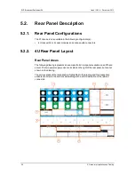
Page 34: ...represents an example of a 4U rear panel available on an XTnano server The two power supply units are located on the right of the rear panel but are not shown on the drawing The various areas of the rear panel are highlighted in the drawing and their respective variants are listed in the sections below along with a short description of the related connectors 26 5 Hardware Installation and Cabling ...

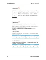
Page 35: ...nano server comes in a version with 4 codec modules a version with 2 codec modules caps on unavailable connectors The following video and codecs connectors layout is available Network Connectors This rear panel part presents the following connectors The Gigabit Ethernet connectors allow the interconnection of servers other EVS and or third party systems into a Gigabit Ethernet network The PC LAN c...

Page 36: ...5 connectors for audio signals input and output in digital format See section Audio Connections on page 30 for more details on the DA 15 connector pinout according to the different configurations The following digital audio connectors layouts are available depending on your configuration BNC Connectors The digital audio module with BNC connectors includes 16 BNC connectors 8 in and 8 out with the ...

Page 37: ...tor to be connected directly to the server and to display PGM and REC channels as configured in the Multicam Configuration window in the Monitoring tab Multiviewer page See the Multicam Configuration manual for a description of the configuration parameters The Loop connector allows the loop of PGM1 on REC1 to be able to use the internal loop feature Lower Part The rear panel part presented below i...

Page 38: ...s 5 4 1 Audio Channels The XTnano server manages up to 64 embedded audio channels depending on the chosen variant and the installed hardware The embedded audio modules and codecs can be used as input or output channels for embedded digital AES EBU or analog audio signals Depending on your server configuration you can find the following audio connectors on the rear panel Digital audio DA 15 connect...

Page 39: ...1 2 AES output 9 10 3 Gnd Gnd Gnd Gnd 4 AES input 3 4 AES input 11 12 AES output 3 4 AES output 11 12 5 Gnd Gnd Gnd Gnd 6 AES input 5 6 AES input 13 14 AES output 5 6 AES output 13 14 7 Gnd Gnd Gnd Gnd 8 AES input 7 8 AES input 15 16 AES output 7 8 AES output 15 16 9 AES input 1 2 AES input 9 10 AES output 1 2 AES output 9 10 10 Gnd Gnd Gnd Gnd 11 AES input 3 4 AES input 11 12 AES output 3 4 AES o...

Page 40: ...1 Analog output 5 3 Gnd Gnd Gnd Gnd 4 Analog input 2 Analog input 6 Analog output 2 Analog output 6 5 Gnd Gnd Gnd Gnd 6 Analog input 3 Analog input 7 Analog output 3 Analog output 7 7 Gnd Gnd Gnd Gnd 8 Analog input 4 Analog input 8 Analog output 4 Analog output 8 9 Analog input 1 Analog input 5 Analog output 1 Analog output 5 10 Gnd Gnd Gnd Gnd 11 Analog input 2 Analog input 6 Analog output 2 Anal...

Page 41: ...pinout is described in the following table Pin DA 15 connector Outputs 1 4 mono 1 Gnd 2 Analog output 1 3 Gnd 4 Analog output 2 5 Gnd 6 Analog output 3 7 Gnd 8 Analog output 4 9 Analog output 1 10 Gnd 11 Analog output 2 12 Gnd 13 Analog output 3 14 Gnd 15 Analog output 4 HARDWARE TECHNICAL REFERENCE MANUAL XTnano Server 12 02 5 Hardware Installation and Cabling 33 ...

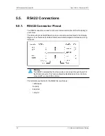
Page 42: ...shielded cable to avoid electromagnetic interference on long distances Warning The RESET command line from the remote control is sent through the pin 5 of the RS422 connector This function should be disabled when the controller on connector 1 is not an EVS controller The technical specification for the RS422 link is as follows 19200 bauds No parity 8 data bits 1 stop bit 34 5 Hardware Installation...

Page 43: ...PC LAN connection Moreover the XTnano is not able to directly send commands to the XTAccess Consequently a backup tool called Xtract is used as the interface to send commands to the XTAccess for file transfer operations and wrapping XT Access is directly connected to the XTnano servers through the Gigabit network It runs on an XP workstation and is controlled in this context by Xtract via XML file...

Page 44: ...960S 48TS Cisco Catalyst 3750X 24TS 3750X 48TS Arista Network 7150S 24 Comparison The models HP Procurve 2510G 24 Cisco Catalyst 2960S 24TS and 2960S 48TS can be used for small setups where no inter VLAN routing is needed The models Cisco Catalyst 2960S 24TD and 2960S 48TD can be used for small setups where 10G uplinks are required but no inter VLAN routing is needed On larger setups both GbE port...

Page 45: ...d The following table gives the list of available uplink modules for the Cisco Catalyst switches of the WS C3750X series Product Number Description C3KX NM 1G Four GbE port network module C3KX NM 10G Two 10GbE SFP ports and Two SFP ports network module C3KX NM 10GT Two 10GB T ports network module Additional Information HP switches have a lifetime guarantee with next business day advance replacemen...

Page 46: ...consists in an opto diode VF 1 1 Volt in series with a 470 ohm resistor Typical switching point 1 4 mA for secure operation i 0 to 0 5 mA opto OFF i 2 5 to 30 mA opto ON imax 30 mA Direct connection to a TTL CMOS signal possible Pin opto to GND and pin opto to the TTL CMOS signal Typical switching point 1 6 Volts for secure operation Vin 0 8 Volts opto OFF Vin 2 2 Volts 2 mA opto ON Vin max withou...

Page 47: ...the device triggering the GPI The ground must be common between the DB 25 connector of the XTnano server and the external device Specifications each pin can be individually configured as an output or an input internal 4K7 pull up to 5 V low level Vi 1 5 Volt U12 74HC245 high level Vi 3 5 Volt U12 74HC245 optional TTL compatible level U12 74HCT245 HARDWARE TECHNICAL REFERENCE MANUAL XTnano Server 1...

Page 48: ...he following applications Setup menu of the Remote Panel IP Director settings GPI and Auxiliary Track tab Specifications normally open contact power off open maximum 1 A maximum 50 Volts typical life time 100 000 000 switchings TTL Outputs GP Out 5 6 7 8 Pin Out 40 5 Hardware Installation and Cabling EVS Broadcast Equipment SA Issue 12 02 A December 2013 ...

Page 49: ...s an output or an input internal 4K7 pull up to 5 V low level Vi 1 5 Volt U12 74HC245 high level Vi 3 5 Volt U12 74HC245 optional TTL compatible level U12 74HCT245 HARDWARE TECHNICAL REFERENCE MANUAL XTnano Server 12 02 5 Hardware Installation and Cabling 41 ...

Page 50: ...d by EVS According to your server version the following setup configurations are available 4U Rack Slot Installed boards 4 video channels 2 video channels 6 RSAS 5 H3X 4 CODA Audio Codec 3 V3X SD HD 2 2 V3X SD HD 1 Genlock V3X SD HD 1 Genlock 1 MTPC 42 6 Boards Description EVS Broadcast Equipment SA Issue 12 02 A December 2013 ...

Page 51: ...ing feature s Full resolution 3D HD on a single V3X module Dual Link HD SDI Genlock There are 2 versions of the V3X board one with genlock one without genlock The genlock model can easily be identified by the presence of 3 quartz synthesizers at the rear of the V3X base board on the right hand side and by the presence of the GLK and PSU OK LEDs on either side of the DIN connector at the center fro...

Page 52: ...and ST2 jumpers when they are not used ST4 only on V3X with genlock Must be set to HiZ or not installed Note that the Genlock Loop connector on the back panel of the server if available must always be terminated with a 75 Ohm load if it is not used ST5 Defines the position of the board inside the server It must be set to 1 for a V3X with genlock and to 2 for a V3X board without genlock depending o...

Page 53: ...nge Off There is a voltage problem V3X COD Modules LEDs The following table lists the LEDs available on then V3X COD modules from left to right LED Color Status Function CPU Green Blinking Indicates CPU activity On There is a problem with the module processor PLAY Green On The module is set in play mode by the software Off The module is set in record mode PVID Green On A valid video signal has bee...

Page 54: ...the SDI input signal SD Loop through for the SDI input signal SD down converted OUT B J4 SDI monitoring output SD SDI monitoring output SD HD CHAR OUT SD HD J5 Not used or SDI input SD in an XREC configuration Not used or SDI input HD in an XREC configuration IN B J6 SDI program output HD SDI program output OUT J7 Not used Not used OUT J8 SDI input SD HD SDI input HD IN J9 Alternate SDI input SD f...

Page 55: ...Connector Layouts HARDWARE TECHNICAL REFERENCE MANUAL XTnano Server 12 02 6 Boards Description 47 ...

Page 56: ...48 6 Boards Description EVS Broadcast Equipment SA Issue 12 02 A December 2013 ...

Page 57: ...put J3 HD SDI program output for right eye 3D HD OUT B J4 SDI monitoring output for left eye 3D HD SD CHAR OUT SD HD J5 HD SDI input for right eye 3D HD IN B J6 HD SDI program output for left eye 3D OUT J7 Not used OUT J8 HD SDI input for left eye 3D HD IN J9 Alternate HD SDI input HD for the internal loop Not wired to the backplane J9 of REC1 only connected to Loop connector Note The loops of the...

Page 58: ...Connectors Layouts 50 6 Boards Description EVS Broadcast Equipment SA Issue 12 02 A December 2013 ...

Page 59: ...t 2 COD B CAM C or PGM 2 Middle codec board slot 3 COD A CAM B or PGM 3 Middle codec board slot 3 COD B CAM A or PGM 4 Server with a Single Codec Board The following table shows how the channels play or record channels are assigned to the codec board and connectors Codec Board Codec Connector Channel Number Lower codec board slot 2 COD A CAM B or PGM 1 Lower codec board slot 2 COD B CAM A or PGM 2...

Page 60: ...h one bus connector on the front side Different audio configurations are available with the audio codec board See Audio Connections on page 30 for details The following LEDs are available on the audio codec board LD 1 3 internal EVS information only LD 4 transfer activity to from the H3X board 52 6 Boards Description EVS Broadcast Equipment SA Issue 12 02 A December 2013 ...

Page 61: ...ed in 4 parts 2 in front 2 in the back Front left GbE module Front right CTL controller module Back left CPU module Back right SDTI module not installed SDTI HARDWARE TECHNICAL REFERENCE MANUAL XTnano Server 12 02 6 Boards Description 53 ...

Page 62: ...ing These LEDs blink alternately every 250 milliseconds to indicate that the processor is running Other LEDs For EVS internal use only Gigabit Connectors The two board Gigabit connectors are connected to the two backplane Gigabit ports The Gigabit connectors must be on a network that supports Jumbo Frames of at least 9014 bytes Ethernet frames See section Switches on page 36 for the list of suppor...

Page 63: ...d as followed 1 6 2 3 4 5 LED Status Function Disk LEDs Off the corresponding disk is not started not spinning On fast blinking green the corresponding disk is starting spinning On steady green the corresponding disk is started and used in the RAID array On slowly blinking green the corresponding disk is started but not used in the RAID array STS On green the RCTL RAID controller is properly boote...

Page 64: ...the interface of the peripheral equipment such as a remote controller with the video hardware The following MTPC board is used Revision A3 A6 with COMMEL HS873 motherboard and a new time code management module with bootable USB 56 6 Boards Description EVS Broadcast Equipment SA Issue 12 02 A December 2013 ...

Page 65: ...io nor video data is saved on this disk The capacity of this drive may vary depending on market availability but the system partition is always set to 1 GB The remaining capacity of this drive is not used 128 MB SDRAM or higher modified The SDRAM used has been modified to suit the system requirements Please contact EVS support for RAMs upgrade Do not use standard PC RAM modules Illustration HARDWA...

Page 66: ...sync generator used in LSM TV mode no effect if the server is only used with a VGA monitor The HPOL jumper can be used to invert or not the VGA HS signal Horizontal Sync to generate the composite output signal TV mode The VPOL jumper can be used to invert or not the VGA VS signal Vertical Sync to generate the composite output signal TV mode The ENVS jumper can be used to enable or not the presence...

Page 67: ... port is NOT an EVS controller Maximum voltage on pin 5 of an RS422 port of the server should not exceed 5 Volt when the corresponding jumper is engaged Applying a higher voltage on pin 5 when the corresponding jumper is engaged will result in permanent electronic damage to the board HARDWARE TECHNICAL REFERENCE MANUAL XTnano Server 12 02 6 Boards Description 59 ...

Page 68: ......

Page 69: ......

Page 70: ...ipment is continuously adapting and improving its products in accordance with the ever changing requirements of the Broadcast Industry The data contained herein is therefore subject to change without prior notice Companies and product names are trademarks or registered trademarks of their respective companies EVS Headquarters Liège Science Park 16 rue Bois St Jean B 4102 Seraing Belgium ...

Reviews: