background image


Assembly and Maintenance 


- 22 - 

PPC-1261 

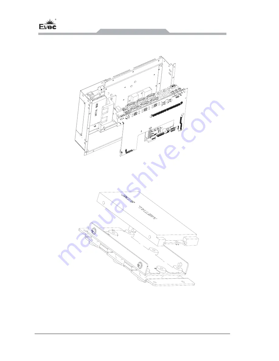
  3. Remove the IO board and motherboard assembly from the chassis rear cover, as 

shown in the picture below; 


4. Finally, separate the IO board from the motherboa


6.3 Removal and Installation of HDD 

rd assembly.   


1. First assemble the HDD onto the HDD bracket, as shown in the above picture. Then 

fix it with the HDD cover lock and install them into the right position as per the 

following picture (CF card is to be directly installed on the HDD cover);   


Summary of Contents for PPC-1261

Page 1: ...Embedded Computer User Manual PPC 1261 12 1 12 1 Panel PC Version C04...

Page 2: ...al personnel During operation please manuals especially the safety warnings The profess ave been trained experiences therefore he she could be aware of the risks of the stem and avoid possible damages...

Page 3: ...eval system or transmitted in any form or by any means mechanical electronic photocopied recorded or otherwise without the prior written permission from the manufacturer Trademarks EVOC is a registere...

Page 4: ...hin the manual usually stands for EVOC s Safety instructions ty losses or individual injury please pay attention to the safety arning triangle PPC 1261 Instruction To avoid proper instructions within...

Page 5: ...t 17 5 3 6 Audio Port 17 1 1 Overview 1 1 2 Product Specifications 1 2 Application Scheme 4 2 1 Transportation 4 2 2 Storage 4 2 3 Opening the Box and Initial 3 Installation 6 3 1 Mounting Method 6 3...

Page 6: ...tion of HDD 22 7 EVOC One Button Recovery Operating Instructions 24 e Button Recovery Operating Instructions 24 r Anti virus Function 28 8 Appendix 29 5 3 7 Power ssembly and Maintenan 6 1 Overall Ass...

Page 7: ...n can be 800x600 LCD screen with common backlight or x768 LCD screen with LED backlight The product features fully sealed fanless super slim design As for software this product supports EVOC y EVOC MB...

Page 8: ...xternal IO Ports Up to six COM ports no CAN port all the COM ports are RS 232 mode by default COM1 COM4 support RS 232 RS 422 RS 485 modes 4 x USB2 0 port 2 x LAN port 2 x CAN port optional CAN port o...

Page 9: ...bility Anti shock 15g 11ms Half sine wave three times for each of the three axes Anti vibration 5 19Hz 1 0mm amplitude 19 200Hz 1 0g three axes Power Features Power consump Input voltage current 9 30V...

Page 10: ...age ping products ic condition should not be stored in open air s Products should not be transpo substances and are not allowed to d mechanical force be stored in package box when it is not used And w...

Page 11: ...doing the initial examination please check whether there are distinct damages t Please of the independe red accessories Please contact the customer service when any unconf ing the Bo d Initial Examin...

Page 12: ...Rack Mount Desktop Embedded Panel Wall Mount VESA Standard Arm Portable Others___________ shown in the left picture before installation remove the rubber plug in the holes Note as for the installation...

Page 13: ...make sure the wall or ceiling shall be able to support at least four times the total weight of the PC including cabinet bracket and additional expansion modules 3 1 2 VESA Standard Supporting Arm Moun...

Page 14: ...Installation 8 PPC 1261 3 2 Outer Appearance and Dimensions Unit mm...

Page 15: ...Installation PPC 1261 9 3 lation Dimensions 3 lation Dimension 3 Instal 3 1 Instal s Unit mm 3 3 2 Dimensions Drawing for Hole Drilling Unit mm...

Page 16: ...ices approved for industrial application can be used When operating the PC hot swappable IO modules USB can be used The IO devices without hot swap function can only be connected when the PC is powere...

Page 17: ...ing the Device to Power Steps to connect the device to power Connect the power cable to the socket and connect the power switch 1 2 Danger Disconnect the power source and data ca lightning storm ble d...

Page 18: ...Instructions 12 PPC 1261 5 Instructions 5 1 Product Outline...

Page 19: ...3 Product Port Definition 5 3 1 Standard DB9 COM ports The carrier board provides six DB9 ports EF EIO 028PPC COM provides six COM orts EF EIO 028PPC CAN provides four COM ports two CAN ports The port...

Page 20: ...5 COM6 9 RI Pin COM Signal Name 1 NC 2 CAN_L 3 CAN_GND 4 NC 5 CAN_GND 6 CAN_GND 7 CAN_H J14 8 NC CAN1 CAN2 9 CAN_VCC 5V Note CAN ports are optical electrical isolation port Their signals GND and VCC a...

Page 21: ...ng RS 232 RS 422 RS 485 default SW3 SW6 SW9 SW12 1 ON 2 OFF 3 OFF 4 NC 1 OFF 2 OFF 3 ON 4 NC 1 OFF 2 ON 3 OFF 4 NC SW4 SW7 SW10 SW13 1 ON 2 OFF 3 ON 4 OFF 1 OFF 2 ON 3 OFF 4 ON 1 OFF 2 ON 3 OFF 4 ON S...

Page 22: ...Speed ACTLED Network Single color Activity Green 1000Mbps green Flash Data being transmitted Orange 100Mbps Off No data being transmitted Off 10Mbps 5 3 6 PS 2 Keyboard Mouse Port Pin Signal Name Pin...

Page 23: ...YNC VGA1 15 DDCCLK 5 3 6 Audio Port Pin Signal Name 1 LINE_OUT Green 2 LINE_IN Blue AUDIO1 3 MIC_IN Red 5 3 7 Power Connector The carrier board provides one 3P horizontal in pi mm which supports singl...

Page 24: ...ol Button Item Description T on used to power e PC he On Off switch butt on th 1 2 wait for the One Button Recovery button After ower on switc ompt will appear D screen to indicate One Button Recovery...

Page 25: ...oof strip 3 Tempered glass or touch 4 Silicone foam 5 LCD assembly 6 Backlight board 7 Touch screen control panel 8 IO board 9 Software dog bracket module 10 CF card or 1 HDD or CF card ody HDD 1 12 C...

Page 26: ...Installing the Motherboard Firstly assemble the mot the IO board following the above picture then install th mbled PCB part ight position i the chassis f en it with screws Note During the installation...

Page 27: ...ve the HDD or CF card module following the above picture then pull out the LCD cable backlight boar le touch control s cable only exists when there is a touch screen from the IO boar 2 Take apart the...

Page 28: ...low 4 Finally separate the IO board from the motherboa 6 3 Removal and Installation of HDD rd assembly 1 First assemble the HDD onto the HDD bracket as shown in the above picture Then fix it with the...

Page 29: ...Assembly and Maintenance PPC 1261 23 2 Follow the above picture to dismantle the HDD or CF card module from the chassis then separate the HDD or CF card from its bracket...

Page 30: ...e last partition of the secondary disk while the default recovery mode is to restore the backup image files in the last partition of the secondary disk to the first partition of the primary disk When...

Page 31: ...10 to save and reboot 2 Enter system backup recovery interface When EVOC One key Recovery function is enabled it will prompt Please Press button RCV for System Recovery within 3 Seconds at that time p...

Page 32: ...g is completed the following information will appear and the system will reboot after 5 seconds Save system success After 5 seconds to reboot Note 1 It is normal if the progress bar is not moving for...

Page 33: ...Please wait with patience 3 If the system prompts Restore system success it indicates that the system has been recovered successfully and the system will reboot after 5 seconds 4 After rebooting set t...

Page 34: ...e from other software including virus therefore it provides excellent defending and safety features The instructions for the anti virus function are as follows 1 During POST period press Del to enter...

Page 35: ...e by luminance control Please refer to the instructions of the display for detailed information The external display is black 1 Please check whether the Power cable or display cable is not connected d...

Page 36: ...odify the booting priority of the setting or include that device into the booting priority not booted or displays Boot device not found not the first priority or the device is not device in the Boot m...

Page 37: ...O Poor contact of the slot frequent installation uninstallation of the PCI or ISA card u card can be used in Poor contact is usually caused by nstable fixing or improper dust proof measures please rem...

Reviews: