background image


Chapter 2 Installation 


- 10 - 

MEC-5003B 

Installing the CF Card 


Loosen the screws on the CF card cover, take off the cover, push in the CF card and 

then fix the CF card cover. When removing the CF card, loosen the screws via screw 

driver and press the CF card socket push rod with hard object to make the CF card 

pop out.   


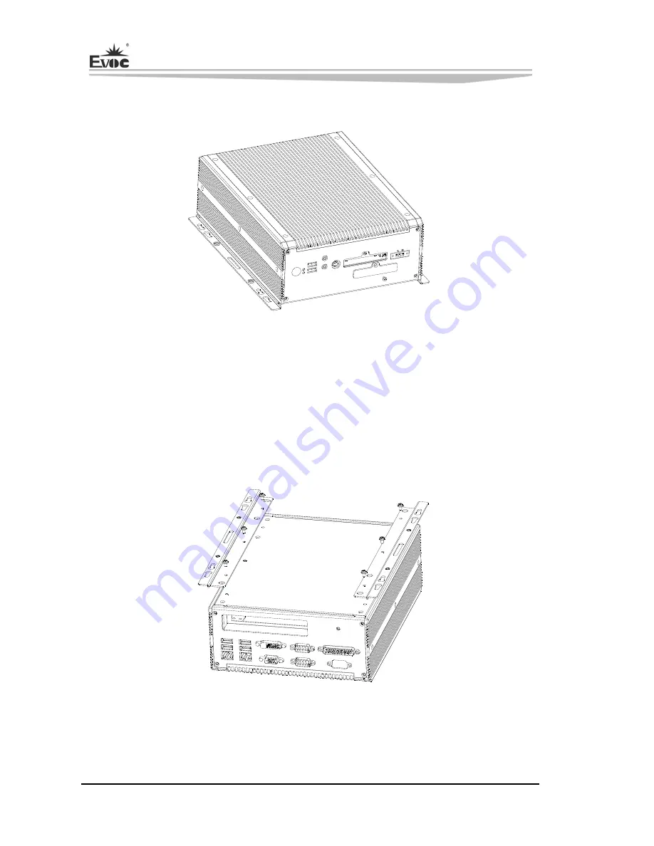
Installing the Wall-mounted Bar 


Align the wall-mounted bars with the mounting holes in chassis and then tighten the 

corresponding screws (as shown in the above figure). 


Summary of Contents for MEC-5003B

Page 1: ...MEC 5003B 低功耗无风扇嵌入式整机 Low Power Embedded Fanless PC Version C00 ...

Page 2: ...tected by copyright No part of this manual may be reproduced stored in any retrieval system or transmitted in any form or by any means mechanical electronic photocopied recorded or otherwise without the prior written permission from the manufacturer Trademarks EVOC is a registered trademark of EVOC Intelligent Technology Co Ltd Other product names mentioned herein are used for identification purpo...

Page 3: ...atic discharge ESD 8 If there s no ESD worktable please take the following measures to prevent damage from electrostatic discharge ESD a Wear a antistatic wrist strap and connect it with the metal part of the corresponding product b Always touch the metal enclosure or frame before touching any components c Keep part of your body in contact with the metal enclosure to discharge the static while han...

Page 4: ...quirements of Transportation and Storage 4 Chapter 2 Installation 5 Product Outline 5 Product Appearance and Installation Dimensions 6 External Connectors 7 Overall Assembly Drawing 8 Installing the Hard Disk 9 Installing the CF Card 10 Installing the Wall mounted Bar 10 Chapter 3 Installing the Drivers 11 ...

Page 5: ...t via power adapter The chassis is molded via al alloy with small form factor compact and solid structure the chassis body also serves as a heat sink to dissipate heat The product can be used in a wide range of harsh environments such as heavy contamination heavy dust and serious EMC etc Featuring small form factor complete functions and strong environment adaptability the product can be widely ap...

Page 6: ...ports LVDS display without hot swap function The maximum resolution supported by LVDS is up to 1600x1200 External IO Six USB2 0 ports Up to six serial ports COM1 and COM2 support RS232 485 422 mode with optical and electric isolation function COM1 also supports Modem wake up function COM3 COM6 are optional 4 in 1 connectors One DVI connector One VGA connector One PS 2 keyboard and mouse connector ...

Page 7: ...ower Consumption 39 W 100 operate 3D Main Performance Mechanical Dimensions Weight and Environment Dimensions 270mm L x 223 4mm W x 94 3mm H Net Weight 5 5Kg Operating Environment Temperature 5 C 50 C Humidity 5 90 non condensing Storage Environment Temperature 40 C 65 C Humidity 5 90 non condensing EMC Limits of radio disturbance are compliant with GB9254 2008 class A Immunity to disturbance is c...

Page 8: ...or carriage During transshipping products should not be stored in open air without protection from the atmospheric conditions Products should not be transported together with inflammable explosive and corrosive substances and are not allowed to be exposed to rain snow and liquid substances and mechanical force Storage Products should be stored in package box when it is not used And warehouse tempe...

Page 9: ...Chapter 2 Installation MEC 5003B 5 Chapter 2 Installation Product Outline ...

Page 10: ...Chapter 2 Installation 6 MEC 5003B Product Appearance and Installation Dimensions ...

Page 11: ...Chapter 2 Installation MEC 5003B 7 External Connectors Front Panel 1 Switch 2 HDD Indicator 3 USB 4 Audio out 5 Keyboard Mouse 6 CF Card Door 7 DC in 8 Power Indicator 9 Mic in ...

Page 12: ... choose corresponding backplanes when using different configurations of the foresaid connectors on backplane 1 For MEC 5003B 0101 and MEC 5003B 0103 no 4 in 1 connector COM3 COM6 is configured and choose the corresponding backplane 2 For MEC 5003B 0102 the 4 in 1 connector COM3 COM6 is configured and choose the corresponding backplane Overall Assembly Drawing ...

Page 13: ... the Hard Disk 1 Assemble the shock absorption pads between the hard disk supporting bracket and the hard disk fixation bracket according to the figure 2 Assemble the hard disk on the hard disk fixation bracket according to the figure tighten the screws to form a hard disk module 3 Assemble the hard disk module with the corresponding studs of the motherboard bracket according to the figure tighten...

Page 14: ...nd then fix the CF card cover When removing the CF card loosen the screws via screw driver and press the CF card socket push rod with hard object to make the CF card pop out Installing the Wall mounted Bar Align the wall mounted bars with the mounting holes in chassis and then tighten the corresponding screws as shown in the above figure ...

Page 15: ...3 Installing the Drivers MEC 5003B 11 Chapter 3 Installing the Drivers Regarding the installation of the driver program and the detailed information of the motherboard please refer to the enclosed CD of the PC ...

Reviews: