background image

Use +/- to preview alarm tone

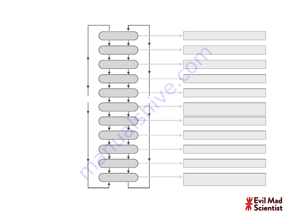
Settings Menu:

Use Snooze and Alarm buttons to 

switch between menu options.

SNOOZE

ALARM

AM/PM,  24 Hr

None,  LED Low,  LED Med., LED High, “Sleep”

X Low, Low,  Medium,  High,  Siren, “Tink”

Switch between values for each menu 

option with the “+” and “–” buttons.

Time Format

Night Light

Alarm Tone

Test Sound

shop.evilmadscientist.com

To enter or exit the settings menu:

Press and hold both “+” and “–” 

buttons for several seconds.

Font Style

Choose from ten different number styles

Clock Style

Four options:  A/P/H suf

fi

or

 seconds “spinner,”

with or without 

fl

ashing separators

Year

Month

Day

Secs.

Calendar: Set the current year

Calendar: Set the current month

Calendar: Set the current day of the month

Time setting: Adjust the seconds of current time

Time And...

Alternate time display with...

None, Date, Seconds, Words

Alpha Clock Five

– Firmware v. 2.0 –

User Interface Guide

Page 2 of 2:

Settings Menu Guide

Summary of Contents for Alpha Clock Five

Page 1: ...r version 2 0 kits Red White and Blue Editions Manual v 2 2 2018 Evil Mad Science LLC An open source hardware software project For support links design files source code additional documentation please visit https wiki evilmadscientist com alpha evilmadscientist com ...

Page 2: ... threaded Digi Key 4334K ND 2 n a 6 32 x 3 8 Phillips Screw McMaster Carr 91772A146 4 LD1 LD5 Machine Pin Socket 10 pin SIL JameCo 102201 10 LD1 LD5 LED Alphanumeric White 2 3 each Betlux BL S230B 13W 12 5 n a Power Supply 9 V 1 A 2 1 mm plug Various 1 n a Chronodot Module Macetech 1 To put your kit together you ll need the build instructions Please visit http wiki evilmadscientist com alpha This ...

Page 3: ...tool Allows fast neat bending of resistor leads Not that many parts like this in the kit but if you like it extra nice 3 Phillips head screwdriver medium size 1 is ideal 4 Screwdriver Alpha Clock Five is a soldering kit You ll need certain tools and supplies to build it 1 Soldering iron 2 Solder 3 Angle Flush Cutters Thin rosin core solder 60 40 solder is easy to use diameter of 025 or so is typic...

Page 4: ...the circuit board Locate these two locations on your circuit board as shown highlighted here Alpha Clock Five Assembly Guide 4 Sanity check This set of instructions is for Alpha Clock Five kits version 2 0 which are based around revisions C D of the circuit board To make sure that you re reading the right set of instructions confirm at this time that your circuit board says Rev C or Rev D at the l...

Page 5: ...mally taped together like the ones shown here Pull the tape straight off to remove it Take one of the resistors and bend it like so Insert it at location R9 the orientation does not matter Next up Soldering tips Our first component type is a 100 ohm resistor part 2 For this first one we ll take it slowly And press it flush to the board Alpha Clock Five Assembly Guide 5 ...

Page 6: ...eeds to be shiny tinned If not melt some fresh solder against it and quickly swipe clean on a wet sponge Place the solder against the joint that you wish to connect Touch the iron to the solder and joint for about one second Count it out one thousand one The solder should melt to the joint and leave a shiny wet looking joint If not let it cool and try again Adding components to the circuit board A...

Page 7: ...t resistor On the back side Bend out the two leads of the resistor Where we perform those steps that we just described Solder both pins to the board Inspect the solder joints Make sure that they look shiny wet and clean to ensure a good connection Clip the excess leads short Bend 7 Alpha Clock Five Assembly Guide ...

Page 8: ...ll Resistor 3 Alpha Clock Five Assembly Guide 8 3 is the only smaller size resistor Up close the color stripes are brown black orange gold Parts identification Next solder parts 3 two 10 k resistors into locations R3 and R4 ...

Page 9: ...a 681 ohm 1 resistor There s just one of these Solder it in at location R2 The resistor s color code is blue gray brown black brown The color code on this resistor is orange yellow black black brown Part 4 is a 340 ohm 1 resistor There s just one of these Solder it in at location R1 ...

Page 10: ... pins of each into place The orientation does not matter You may find it helpful to slightly bend out one or two of the pins of each on the bottom side to hold them in place while you solder Part 7 is a single zerohm jumper it looks like a resistor with a single black stripe Install it as you would a resistor at location JP1 After installing these three components advance to Step 10 skipping Step ...

Page 11: ...tor pack s body These two components go into locations RP1 and RP2 on the circuit board Note however that you need to place them with a specific orientation Pin 1 of each resistor pack needs to be inserted into the Pin 1 hole of locations RP1 and RP2 The Pin 1 holes are the ones with the square pads indicated here with arrows After inserting parts 6 with the correct orientation solder all six pins...

Page 12: ... into the circuit board matching the two ends with the notches This is 8 the 40 position socket for the microcontroller Locate the polarity marking notch at one end of the socket Assembly Step 10 The 40 pin IC Socket 12 Alpha Clock Five Assembly Guide To ensure good positioning rest the circuit board flat on top of the socket The socket pins will protrude but only very slightly through the circuit...

Page 13: ... same method used for the 40 pin socket Again take care to match the notches to those on the circuit board Parts 9 and 10 are 24 pin and 16 pin DIP Sockets respectively Blue White Alpha Clock Five kits also include a 11 a 14 pin DIP socket Note that each has a notch at one end to mark the polarity Then solder the rest of the socket pins To begin with solder just two opposite corner pins of the 40 ...

Page 14: ...while soldering On the top side make sure that the header sits flush to the circuit board If not flip it back over and melt the joint while pressing down on the circuit board to snap the header into place Assembly Step 12 Six pin DIL ISP Header 14 Alpha Clock Five Assembly Guide Solder just one pin to begin with Then solder the other five pins ...

Page 15: ...n M1 There are actually two rows of holes at M1 Note that the headers go in the outer positions Insert the two headers In this step we add the sockets that allow Alpha Clock Five to be connected to a real time clock module e g Chronodot Assembly Step 13 RTC Sockets 15 Alpha Clock Five Assembly Guide And flip the board over to rest on them holding them in place for soldering Solder one pin of each ...

Page 16: ... Alpha Clock Five kits include a 2 1 x 5 5 mm jack Place it at location J1 on the top side of the circuit board Solder one pin of the connector the side pin to hold it in place The larger metal here can take a while to heat up to about 8 s On the bottom side solder all three pins in place Note that it is not necessary to fill the holes all the way with solder ...

Page 17: ...Guide 17 Parts 15 are two little 18 pF ceramic capacitors little yellow beads with two pins There are two similar types of ceramic capacitors in the kit so these ones are marked with a black stripe Solder these two capacitors on the board at locations C5 and C6 ...

Page 18: ...r looking 0 1 uF ceramic capacitors but there are more of them and without the black stripe For Red Alpha Clock Five Install six of these capacitors in locations C1 C2 C3 C7 C8 and C10 For BLUE White Alpha Clock Five Install seven of these capacitors in locations C1 C2 C3 C7 C8 C10 and C12 ...

Page 19: ...tep 17 Quartz Crystal Alpha Clock Five Assembly Guide 19 17 Install part 17 a 16 MHz quartz crystal Its two pins go in the outer two holes of the location marked XTL Solder both pins in place much like a resistor ...

Page 20: ...rst one goes in location J2 on the circuit board oriented so as to match the drawing on the circuit board Parts 18 are six pin single inline SIL right angle RA headers Assembly Step 18 Six pin SIL RA Headers 20 Alpha Clock Five Assembly Guide Repeat the procedure to add a second header at location J5 with the pins facing towards the edge of the board as shown ...

Page 21: ...embly Guide 21 Part 19 is a small white LED Note that this component has one long lead and one short lead Install the LED in location D2 near the top middle of the board Orientation matters The long lead of the LED goes into the square hole of location D2 ...

Page 22: ...the kit The six transistors 20 and the voltage regulator 21 In the next step Step 21 you will install the six transistors So at this time identify the one voltage regulator and set it aside leaving you with those six transistors for the next step Voltage Regulator 21 Transistors 20 quantity 6 Voltage Regulator 21 Transistors 20 Identification Markings include X2220 Vertical text Six of these Ident...

Page 23: ...e transistors do not seat fully flush to the circuit board but rather slightly above it like so Do not force them down further Assembly Step 21 The Transistors Alpha Clock Five Assembly Guide 23 Install all six transistors matching the orientation of that flat face to the outline on the circuit board and then soldering them into place ...

Page 24: ...the next page Step 23 24 For BLUE or WHITE Alpha Clock Five only Part 21 is the voltage regulator that you identified in Step 20 It goes in location U4 To install it follow the same procedure that you used with the transistors in the last step Match the flat face of the regulator to the outline on the circuit board and solder it into place ...

Page 25: ...e side facing up bend the leads down as shown Solder in the first capacitor at location C4 in the upper right corner of the board Make sure that the side of the capacitor faces the stripe on the circuit board as shown above For Red Alpha Clock Five Kits Install one more capacitor into location C9 Leave C11 unpopulated For Blue or White Alpha Clock Five Kits Install two more capacitors at locations...

Page 26: ... right angle tactile button switches Snap the button into the location and make sure that it sits fully flush to the board Solder all four pins in place Repeat for each of the switch locations S1 S5 Here is what one of the button locations looks like ...

Page 27: ...o indicate its polarity Insert the speaker making sure that the pin goes into the matching hole on the circuit board Solder both pins and clip the leads Remove the Kapton tape seal if present It may also have a piece of yellowish Kapton tape that seals the hole on the top Locate the speaker location L1 next to the power jack and identify the side ...

Page 28: ... chip YES no Assembly Step 26 Add the chips Alpha Clock Five Assembly Guide Part 25 Part 26 Part 27 Press the chips down firmly to seat them fully into their sockets Like the sockets each chip has a notched end to indicate its polarity Align that notch to the notch on the socket and on the circuit board Parts 25 27 are the integrated circuits which go in sockets U1 U3 respectively 28 Blue White Al...

Page 29: ...re threaded angle brackets Parts 30 are matching Phillips head screws Put two of the screws through the clearance holes in the lower half of the bottom side of the circuit board Loosely thread each screw into an angle bracket on the other side of the board Do not tighten them yet ...

Page 30: ...Square the two angle brackets with respect to each other and with respect to the circuit board as you tighten the screws It may be helpful to hold the assembly against a hard flat surface while you do so Tighten the screws very securely to lock the angle brackets in place ...

Page 31: ...numeric LED displays which will make it harder to access the back side of the circuit board So this is a great time to make sure that everything looks good so far U4 Your circuit board should look approximately like this Every component should be populated except for the following locations which are left empty J3 C11 C12 R6 R7 RP2 RP5 RP1 RP6 U5 D1 R8 Separate note These display sockets along the...

Page 32: ...c LED displays which will make it harder to access the back side of the circuit board So this is a great time to make sure that everything looks good so far Your circuit board should look approximately like this Every component should be populated except for the following locations which are left empty J3 JP1 R6 R7 RP3 RP4 D1 R8 Separate note These display sockets along the edges are shown soldere...

Page 33: ...re straight vertical and parallel on each display If necessary gently bend them into place Parts 32 are the five alphanumeric LED displays in red white or blue The display segments are filled with a diffusing plastic which may be tinted for red LED displays or yellowish for white LED displays From this point forward the instructions are the same Good Bad Also bad White LED Displays Red LED Display...

Page 34: ...in the kit The socket strips press onto the pins of the alphanumeric LED displays with gentle pressure For reference the socket strips should slide very far down onto the pins as far down as shown here Repeat for both strips of each LED display Slide one of the 10 position sockets onto the ten pins on one side of an LED display Make sure that it seats all the way down as shown previously ...

Page 35: ...ether and that the pins are aligned nicely The socketed LED displays will go in locations LD1 LD5 on the back side of the circuit board If the displays do not sit neatly go back and make sure that 1 The LED pins are straight and vertical Step 28 and 2 The sockets are fully seated Step 29 With all of the LED displays sitting in place check that the front faces are reasonably level and that the gaps...

Page 36: ...ially Start with the middle display As with some of our earlier parts the machine pin sockets only barely reach through the circuit board As with earlier sockets initially solder just the two opposite corner pins Double check that the socket is properly seated and then solder the remaining socket pins in place ...

Page 37: ...34 Add remaining alphanumeric displays Alpha Clock Five Assembly Guide 37 Install the next two LED displays at LD2 and LD4 the same way Finally install the outer two alphanumeric LED displays at locations LD1 and LD5 ...

Page 38: ...ssembly Guide 38 Connect the power supply 33 and apply power to your clock Red versions of Alpha Clock Five come with a 5V power supply whereas blue white versions come with a 9V power supply If all goes well it will say HELLO WORLD in a few seconds ...

Page 39: ...ide 39 With the power supply plugged in hold down both the Time and Alarm buttons for 4 seconds to enter the LED Test mode This will generate a slowly changing LED test pattern that will light up every LED on the front face to help highlight any assembly issues ...

Page 40: ... Guide 40 Chronodot RTC module Slide the battery into the battery holder on the Chronodot noting the polarity side on the battery towards the side on the holder Install the Chronodot in the headers at location M1 on the circuit board labeled Opt RTC Make sure that all eight pins line up correctly into the sockets and that the text on the Chronodot is right side up i e oriented the same way as the ...

Page 41: ...sed Accordingly please take care in the following steps not to over tighten the fasteners that hold the case together Front 35 Top 37 Back 36 Bottom 38 Black screws 4 40 40 Hex Nut 4 40 39 6 32 screws 30 The four acrylic case pieces may be wrapped in protective paper or plastic Carefully peel off this wrapping material The front is either smoke gray or tinted depending on the color of your Alpha C...

Page 42: ...wo through holes in the case bottom Orient the case bottom as shown up against the bottom of the circuit board with the back tabbed side facing up Thread each screw into the corresponding angle bracket Once both screws from the case bottom are in place tighten them firmly but take care not to over tighten Insert one of the 6 32 screws up from the bottom side of each hole ...

Page 43: ...ee T slots on the back side of the case bottom Place the case back the transparent gray piece over the tabs on the case bottom While supporting its weight insert three of the black 4 40 screws through the top and into the nuts Tighten them just until they support the weight of the case back ...

Page 44: ...e got thus far the case bottom and back sides are attached Stand the case up on end and slide the top into place One at a time insert one of the hex nuts into one of the three T slots and fix it in place with a black 4 40 screw As before keep it loose Only tighten the screws enough to roughly hold the nuts in place ...

Page 45: ...t bottom of the clock Position the case front in place with the curved footed side towards the bottom of the clock Insert three more screws through the front plastic to engage the hex nuts Hold the hex nuts flush against the LED displays while you tighten the screws And on this side tighten the three screws firmly ...

Page 46: ...l screws If you have trouble getting the case front to reach the case top the screws on the back side are probably too tight try loosening them a bit One at a time add the final three hex nuts and screw each one into place with one of the black 4 40 screws ...

Page 47: ... four top buttons at this time If everything is in the right place the buttons will respond with a friendly click to gentle pressure If not if the top piece is too high or too low you may need to slightly loosen one or more of the front top screws to move the case top where it needs to go ...

Page 48: ... 3 Tighten the screws here on the rear bottom 4 Tighten the screws here on the front bottom Once you finish tightening the screws double check the buttons to make sure that each is working correctly Also you may notice that the circuit board and LED displays do not sit completely vertical in the case but lean back at a slight angle This is normal and expected ...

Page 49: ...se see the User Interface Guide on the following page to learn how to operate your clock Please visit our wiki site https wiki evilmadscientist com alpha for much more additional documentation For technical support please visit our Clock support forum http www evilmadscientist com forum ...

Page 50: ...larm time using Adjust time using Hold pair Simultaneous press and hold 4 seconds Show firmware version Enter or leave LED test mode Simultaneous press and hold 2 seconds Enter or leave settings menu Alpha Clock Five Usage Notes shop evilmadscientist com Reset button Test backup battery Alpha Clock Five Firmware v 2 0 User Interface Guide Page 1 of 2 Main Button Usage ...

Page 51: ... or exit the settings menu Press and hold both and buttons for several seconds Font Style Choose from ten different number styles Clock Style Four options A P H suffix or seconds spinner with or without flashing separators Year Month Day Secs Calendar Set the current year Calendar Set the current month Calendar Set the current day of the month Time setting Adjust the seconds of current time Time A...

Page 52: ... towards the location on the circuit board marked Black Any time that you connect the computer to the clock the clock is likely to restart However you can use the computer to set the time on Alpha Clock Five or to display text on the alphanumeric display See the Alpha Clock Five documentation wiki for more information about the serial protocol Appendix Hooking up to a computer Alpha Clock Five Usa...

Reviews: