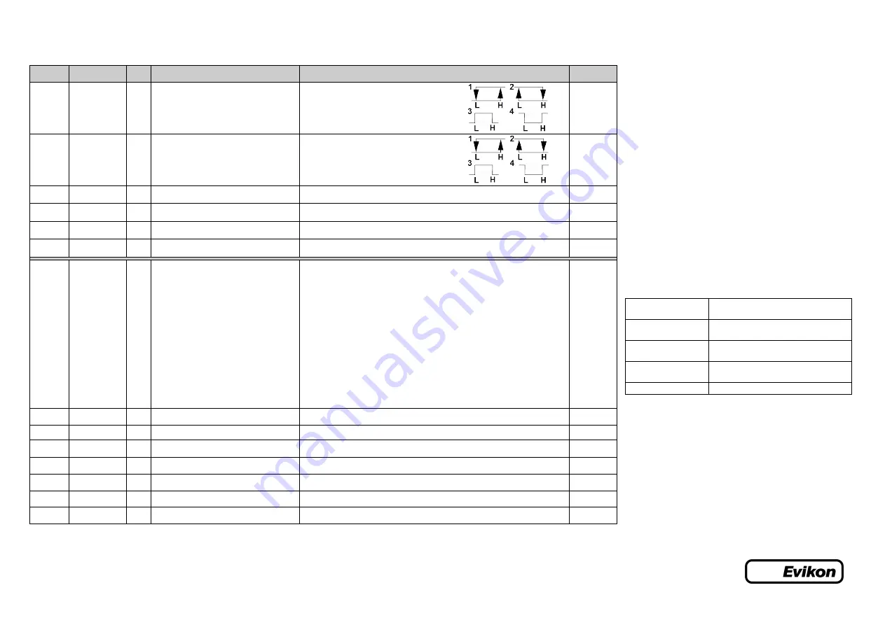
E2648 series Modbus holding registers (part 3)
Register addresses are shown 0-based, Addr in hexadecimal, Reg in decimal format.
Modbus holding register numbers MHR are shown in decimal 1-based format, and may be addressed either from 00001 or 40001 base.
Addr
Reg / MHR
RW
Description
Supported values (dec)
Default
0x00DB
219 / 40220
RW
Control logic for relay RE1
0 – none
1 – relay on at high values
2 – relay on at low values
3 – relay on at values within the range
4 – relay on for the values out of the range
0
0x00DC
220 / 40221
RW
Control logic for relay RE2
0 – none
1 – relay on at high values
2 – relay on at low values
3 – relay on at values within the range
4 – relay on for the values out of the range
0
0x00DD
221 / 40222
RW
LOW setpoint for relay RE1
0...65535 (gas units)
see
Specifications
0x00DE
222 / 40223
RW
HIGH setpoint for relay RE1
0...65535 (gas units)
see
Specifications
0x00DF
223 / 40224
RW
LOW setpoint for relay RE2
0...65535 (gas units)
see
Specifications
0x00E0
224 / 40225
RW
HIGH setpoint for relay RE2
0...65535 (gas units)
see
Specifications
0x00FF
255 / 40256
RW
Sensor, analog outputs, LED and buzzer
status
bit[0]=0/1 – sensor present/absent, read-only!
bit[1]=0/1 – analog outputs deactivated/activated,
bit[2]= 0/1 – in case the sensor is absent, turn signaling off/on analog output1,
bit[3]=0/1 – in case the sensor is absent, turn on signaling with low current/high
current on analog output1; if bit[2]==0 this bit will be ignored,
bit[4]=0/1 – in case of sensor absent, turn signaling off/on analog output2
bit[5]=0/1 – in case of sensor absent, turn on signaling with low current/high current on
analog output2; if bit[4]==0 this bit will be ignored,
bit[6]=0/1 – current/voltage output detected on output1, read-only!
bit[7]=0/1 – current/voltage output detected on output2, read-only!
bit[8]=0/1 – LED deactivated/activated,
bit[9]=0/1 – buzzer deactivated/activated
bit[10]=0/1 – LED is on/off in normal condition
bit[11]=0/1 – LED and buzzer syncing off/on with RE1
bit[12]=0/1 – LED and buzzer syncing off/on with RE2
user defined
0x0101
257 / 40258
R
Raw gas sensor data
ADC data 0...4095
0x0102
258 / 40259
R
Measured temperature, °C×100
signed integer, -4000...+12500 (-40,00...+125,00 °C)
0x0103
259 / 40260
R
Gas concentration, gas units
signed integer, -32000...+32000 (gas units)
0x0105
261 / 40262
RW
0% value for analog output 1
-32000...+32000 (gas unit/°C)
user defined
0x0106
262 / 40263
RW
100% value for analog output 1
-32000...+32000 (gas unit/°C)
user defined
0x0107
263 / 40264
RW
0% value for analog output 2
-32000...+32000 (gas unit/°C)
user defined
0x0108
264 / 40265
RW
100% value for analog output 2
-32000...+32000 (gas unit/°C)
user defined
* – The new value is applied after restart.
** – Broadcast slave ID 0 can be used to assign a new ID to device with unknown ID. When addressing by ID 0 the device shall be
the only Modbus instrument in the network. The device will not respond to Master command when addressed by ID 0.
*** – This value is dynamic and not kept in EEPROM after restart
NOTE 1
Relay setpoints should be set within 5-95% of the detection
range.
NOTE 2
Sensor absense signalling (bits from [2] to [5]) is available only for
sensors with digital interface ( e.g.-CO2 10K, -O2-L).
NOTE 3
LED/buzzer signalization (if activated):
Detectable sensor
absence or malfunction
0.5Hz (90% off, 10% on) light and/or sound
signal
Relay1 turned on
1 Hz (50% on, 50% off) light and/or sound
signal, depending on bit[8], bit[9] and bit[11]
Relay2 turned on
2 Hz (50% on, 50% off) light and/or sound
signal, depending on bit[8], bit[9] and bit[12]
Modbus response
the light signal is modulated with short on-off
pulses, even single Modbus cycle is visible
Normal operating
continuously on/off depending on bit[10]
NOTE 4
We recommend to set the difference between the upper and
bottom limits of the output scale not narrower than 20% of detection
range (for CO detectors the scales down to 5% of range are
allowed). In any case, do not set the output scale below the tenfold
resolution of the device.


