background image

7882J2KX-IPASI  

Single Channel J2K Encoder/Decoder 

Page - 54


Revision 1.0


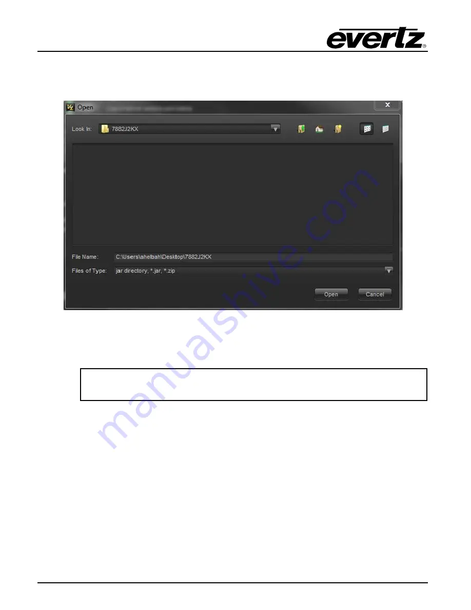
A window will appear, as shown in Figure 6-2. Navigate to the location of the new JAR file and double 
click to select the file. The window will automatically close and the update will be applied in the 
background.  


Figure 


6-2 : VistaLINK

®

 PRO – Applying JAR Updates 


You will be prompted to restart the server to enable the change to take effect. Apply as many JAR 
updates as required before restarting the server. 


NOTE: You may confirm that all updates have been successfully applied by 

selecting from the menu Tools>View>Show/Hide Product update log. 


Shutdown the server by selecting from the menu: 

File>Shutdown Server

. Now re-open the server, it is 

normal for the start up to take marginally longer while each individual update is being applied. Once 
complete, you may restart the VLPro Clients. As the Client restarts you will experience a short delay 
while the update is applied. A prompt will appear confirming that the updates have been applied. 


Summary of Contents for 7882J2KX-IPASI

Page 1: ...roperty of Evertz Microsystems and is intended solely for the use of purchasers of the 7882J2KX IPASI series product Evertz Microsystems expressly prohibits the use of this manual for any purpose other than the operation of the 7882J2KX IPASI series product Due to on going research and development features and specifications in this manual are subject to change without notice All rights reserved N...

Page 2: ...This page left intentionally blank ...

Page 3: ...ird grounding prong The wide blade or the third prong is provided for your safety If the provided plug does not fit into your outlet consult an electrician for replacement of the obsolete outlet Protect the power cord from being walked on or pinched particularly at plugs convenience receptacles and the point where they exit from the apparatus Only use attachments accessories specified by the manuf...

Page 4: ... Class A digital device pursuant to Part 15 of the FCC Rules These limits are designed to provide reasonable protection against harmful interference when the equipment is operated in a commercial environment This equipment generates uses and can radiate radio frequency energy and if not installed and used in accordance with the instruction manual may cause harmful interference to radio communicati...

Page 5: ...rt 6 3 2 CARE AND HANDLING OF OPTICAL FIBER WHEN USING SFP MODULES 7 3 2 1 Handling and Connecting Fibers 7 3 3 HARDWARE INSTALLATION 8 3 3 1 Three Different Ways to Control and Configure the 7882J2KX IPASI 8 3 3 2 Module Installation 8 3 3 3 Control Port Configurations for the 7882J2KX IPASI 9 4 WEB INTERFACE 11 4 1 SYTEM TAB 12 4 2 PRODUCT FEATURES TAB 15 4 3 DECODER CONTROL TAB 16 4 4 DECODER A...

Page 6: ... DECODER MONITOR TAB 41 5 6 INPUT AUDIO PROC CONTROL 43 5 7 ENCODERS CONTROL TAB 44 5 8 ENCODERS MONITOR TAB 46 5 9 PRESET TAB 47 5 10 SYSTEM NOTIFY TAB 48 5 11 ENCODER NOTIFY TAB 49 5 12 DECODERS NOTIFY TAB 50 6 UPGRADE PROCEDURES 53 6 1 UPDATING VLPRO SERVER JAR FILE 53 6 2 FIRMWARE UPGRADE 55 6 3 FIRMWARE UPGRADE USING WEBEASY 55 6 4 FIRMWARE UPGRADE USING VISTALINK 57 ...

Page 7: ...b 28 Figure 4 16 WebEASY Decoder Notify Tab 29 Figure 5 1 VistaLINK System Tab Part 1 32 Figure 5 2 VistaLINK System Tab Part 2 34 Figure 5 3 VistaLINK Product Features Tab 35 Figure 5 4 VistaLINK Decoder Control Tab Part 1 37 Figure 5 5 VistaLINK Decoder Control Tab Part 2 39 Figure 5 6 VistaLINK Decoder Audio Control Tab 40 Figure 5 7 VistaLINK Decoder Monitor Tab 41 Figure 5 8 VistaLINK Input A...

Page 8: ...7882J2KX IPASI Single Channel J2K Encoder Decoder Page iv Revision 1 0 This page left intentionally blank ...

Page 9: ...only warranty offered by Evertz in relation to this product is the Evertz standard limited warranty stated in the sales contract or order confirmation form Although every attempt has been made to accurately describe the features installation and operation of this product in this manual no warranty is granted nor liability assumed in relation to any errors or omissions unless specifically undertake...

Page 10: ...7882J2KX IPASI Single Channel J2K Encoder Decoder Page vi Revision 1 0 This page left intentionally blank ...

Page 11: ...h a frame controller for multiple control options For those mission critical applications the 7882J2KX IPASI can be intelligently managed using the Evertz Compression Systems Manager CSM software which offers complete provisioning monitoring and redundancy management of the contribution compression head end Features Benefits 1x 3G HD SD SDI JPEG2000 Encode 1x 3G HD SD SDI JPEG2000 Decode Supports ...

Page 12: ...7882J2KX IPASI Single Channel J2K Encoder Decoder Page 2 Revision 1 0 Figure 1 1 7882J2KX IPASI Encoder Block Diagram Figure 1 2 7882J2KX IPASI Decoder Block Diagram ...

Page 13: ...UTPUT STANDARDS Standard ASI per DVB TR 101 891 Max 213Mb s Number of Outputs 4 Connectors BNC IEC 61169 8 Annex A 2 3 ETHERNET Control Port 1x GbE Control Port RJ 45 Data Ports 2x GbE Data Ports SFPTR RJ45 SGM AV 2 4 COMPRESSION AND ENCAPSULATION SPECIFICATIONS Encapsulation RTP SPTS Video Compression JPEG 2000 422 10 BIT 2 5 AUDIO SPECIFICATIONS Number of Channels 16x Channels of Embedded PCM su...

Page 14: ...ted HTTP with full control SNMP VistaLINK remote control and monitoring via Frame Controller 2 7 ELECTRICAL Input Voltage Auto ranging 100 240VAC Power 48W EMI RFI Complies with FCC regulations for class A devices Complies with EU EMC directive 2 8 PHYSICAL NUMBER OF SLOTS 7800FR 2 7800FR QT 2 7801FR 2 3700FR 2 ...

Page 15: ... J2K encoder ASI output Decoder or Video Processing HD SD SDI Loopout OUTPUT 2 J2K encoder ASI output Decoder or Video Processing HD SD SDI Loopout OUTPUT 3 J2K encoder ASI output Decoder or Video Processing HD SD SDI Loopout OUTPUT 4 J2K encoder ASI output Decoder or Video Processing HD SD SDI Loopout DATA 1 2 There are two SFP cages for streaming out J2K or inputting a J2K stream for decoding RJ...

Page 16: ...ut information in Table 3 1 or Table 3 2 for the current RJ 45 standards AT T 258A EIA TIA 568A or EIA TIA 568B colour coding listed Also refer to the notes following the table for additional wiring guide information Figure 3 2 RJ 45 Connector Pin Out Locations Pin 1 Pin Signal EIA TIA 568A AT T 258A or EIA TIA 568B 10BaseT or 100BaseT 1 Transmit White Green White Orange X 2 Transmit Green White o...

Page 17: ...k is idle the devices also send a link test signal to one another to verify link integrity The 7882J2KX IPASI Ethernet port is fitted with two LEDs to monitor the Ethernet connection 3 2 CARE AND HANDLING OF OPTICAL FIBER WHEN USING SFP MODULES 3 2 1 Handling and Connecting Fibers Never touch the end face of an optical fiber Always keep dust caps on optical fiber connectors when not connected and ...

Page 18: ... electricity It is therefore recommended that an ESD strap be worn Locate on a frame chassis two adjacent vacant slots Unpack the 7882J2KX IPASI and separate the rear plate module from the main card Locate on the rear of the rack the two slots and remove the blanking panels Insert the rear plate module into the back of the chassis and secure using the four screws provided Figure 3 3 7800 Chassis I...

Page 19: ...C frame controller to control the module this step is not necessary for setting the control port on the 7882J2KX IPASI 1 Connect the Evertz serial upgrade cable ribbon cable to the 2x3 header at the front edge of the 7882J2KX IPASI card 2 Start a terminal program and configure the port settings Figure 3 4 COM Port Serial Port Settings 3 Boot up module and a Tera Term platform login prompt enter cu...

Page 20: ...trated below will appear Set the desired network addresses per your requirement After entering all settings choose Exit two times to save configurations and get back to main menu The card must be rebooted for all the network settings to take effect Pull module out and in to reboot when all changes have been completed and saved Figure 3 6 COM Port Network Settings ...

Page 21: ...can be completely configured using the web interface Simply type the IP address of the control port in the web browser Figure 4 1 WebEASY Login Menu Login and password are root and evertz respectively Due to the size of the certain menu tabs we will be breaking up screen tab images into multiple images Some of the screen shots will also require the user to zoom in to see the image more clearly ...

Page 22: ...device must be rebooted for the changes to take Reboot can be pressed at the bottom of this System tab after all changes are made Control Port IP Address This control allows the user to set the IP address on the Control Port This control will also display the currently set IP address Netmask This control allows the user to set the Netmask for the Control Port IP address This control will also disp...

Page 23: ... Server IP This parameter allows the user to assign the external syslog server IP address This will be the address of a PC with the syslog server software installed ex Kiwi Syslog Server Data Port Control must reboot in order for new settings to take effect IP Address This control allows the user to set the IP address on the Data Port This control will also display the currently set IP address Net...

Page 24: ...r returns the link status for the Data Port The status could be either Up or Down Link Info When the link is Up this parameter returns link speed duplex mode information for Data Port Receive Bandwidth When the link is Up this parameter returns the receive bandwidth currently being read on the Data Port Reading is in kbps Transmit Bandwidth When the link is Up this parameter returns the transmit b...

Page 25: ...tive power cycle 4 2 PRODUCT FEATURES TAB The 7882J2KX IPASI has the ability to enable features by adding updating applicable licenses Please contact Evertz Microsystems Ltd for any additional License generation along with Product Serial Number and Product MAC address Figure 4 4 WebEASY Product Features Tab Product License Product License File This parameter allows the user to apply new License ke...

Page 26: ... disabled means the license key is not installed 4 3 DECODER CONTROL TAB Figure 4 5 WebEASY Decoder Control Tab Part 1 Output Control Force Interface This is an engineering control Please leave it configured to the default setting Loss of Video Output This control allows the user to select the decoder output on a loss of video output Input Program Control Program Tuning Mode Options are Auto PID S...

Page 27: ...n the PAT o Lowest program number will select the program with the lowest Program ID o Specific Program Select Program Number Select This control is used to specify the program number for decoding Manual PID Control When Program Tuning Mode is set to Manual PID Select only then will these values be applied Video PID Select 2 8190 This control is used to specify the video PID for decoding PCR PID S...

Page 28: ...ut source for the Decoder Options are Data 1 Data 2 ASI 1 or ASI 2 IP Address This control is used to specify the multicast address to be received UDP Port Number This control is used to specify the associated UDP port number for the multicast Initial IGMP Version This control is used to specify the initial IGMP version to use Options are V2 or V3 IGMPV3 Mode This control is used to specify the ty...

Page 29: ...disabled This control is used to manually select which input profile to use Options are Main or Backup Wait Switch Time after Loss of Primary Input This control is used to set the amount of time in seconds on a loss signal of the primary input before switching over to the Backup feed Wait Switch Time after Loss of Backup Input This control is used to set the amount of time in seconds on a loss sig...

Page 30: ... Input Monitor Status This field displays if an input is detected on the decoder Bitrate This field displays the detected bitrate for the input Input Packet Framing This field displays the type of packet framing detected Options are RTP or UDP Input Num TS Packets This field displays the number of TS packets received in one IP packet ...

Page 31: ... format Video Resolution This field displays the video resolution Video Frame Rate This field displays the frame rate Audio Monitor For Audio 1 4 Sampling Rate This field displays the sampling rate on the audio Number of Channels This field displays the number of audio channels being decoded Decoder Demux Audio Monitor For Demux Audio 1 4 PID This field displays PID number used for the audio demux...

Page 32: ...allows the user to select any embedded audio channel 1 16 or Mute When Audio Proc is enabled the respected input channel will be routed to the Encoder audio source channel as defined by the user 4 7 ENCODERS CONTROL TAB Figure 4 10 WebEASY Encoders Control Tab Part 1 Output Configuration IP Address This parameter allows the user to select a streaming output IP address for the Encoder Can be a Mult...

Page 33: ...ows the user to select a streaming output IP address for the Contribution Backup Encoder Can be a Multicast or Unicast address Backup UDP Port Number SFP 2 This parameter allows the user to select the destination UDP port number of the backup streaming output Video Control Encoder SDI Input This control selects the SDI input to use for encoding Encoder Controls Basic PMT PID This parameter allows ...

Page 34: ...o 4 PID The 7882J2KX IPASI has 4 x Audio Pids These parameters allow the user to select the Audio PID number Audio MUX Control For Audio 1 to 4 First AES On Output This parameter allows the user to select the de embedded audio pair on the audio encoder Total AES On Output This parameter allows the user to set the number of AES pair on a certain PID ...

Page 35: ...ONITOR TAB Figure 4 12 WebEASY Encoders Monitor Tab Video Monitor Video Status This parameter displays the detected video resolution of the encoder Audio Monitor Audio Status This parameter displays audio channel pairs that are present at the input It monitors the audio control packets ...

Page 36: ...ept the following Control Port IP address Netmask and Gateway Data Port 1 and 2 IP address Netmask and Gateway Syslog Configuration Presets SNMP Trap destinations Faults and Video Notify status Preset Recall This control will take the stored 7882J2KX IPASI settings and apply them When recalling a preset all parameters will be set except the following Control Port IP address Netmask and Gateway wil...

Page 37: ...a trap if there is a fault generated by a link loss on SFP 1 when enabled SFP External Link Fault Present monitor displays if there is a fault condition on the SFP 1 Green indicates healthy while red indicates a fault SFP 2 External Link This control sends out a trap if there is a fault generated by a link loss on SFP 2 when enabled SFP External Link Fault Present monitor displays if there is a fa...

Page 38: ...r frame increments As in 1 4 frames and 10 40 frames The range is 1 4 frames to 2499 9996 frames Encoder Notify Video Present This is the video presence detected by the encoder By default a grey test pattern is generated when input video is removed Hence the video presence will still be active This control sends out a trap if there is a fault generated by a lost video signal when enabled Video Fau...

Page 39: ... condition on the TS Input Missing Green indicates healthy while red indicates a fault TS Sync Byte Missing This control sends out a trap if there is a fault generated by a missing TS Sync Byte when enabled Decoder Input Faults displays if there is a fault condition on the TS Sync Byte Missing Green indicates healthy while red indicates a fault Video PID Missing This control sends out a trap if th...

Page 40: ...7882J2KX IPASI Single Channel J2K Encoder Decoder Page 30 Revision 1 0 This page left intentionally blank ...

Page 41: ...J2KX IPASI and VistaLINK PRO 1 7800FC Frame Controller and 7882J2KX IPASI with appropriate Jar file Open VistaLINK PRO and click on the refresh tree icon Expand the hardware tree by clicking on the button The 7800FC should show up and the number of 7882J2KX IPASI cards installed after it in the tree formation 2 Using the 7882J2KX IPASI control port and appropriate Jar file Open VistaLINK PRO and c...

Page 42: ...1 SYSTEM TAB Figure 5 1 VistaLINK System Tab Part 1 Note For IP address settings on Control and Data ports after applying any changes the device must be rebooted for the changes to take effect Reboot can be pressed at the bottom of this System tab after all changes are made ...

Page 43: ...er Syslog Server IP This parameter allows the user to assign the external syslog server IP address This will be the address of a PC with the syslog server software installed ex Kiwi Syslog Server Data Port Control must reboot in order for settings new to take effect IP Address This control allows the user to set the IP address on the Data Port This control will also display the currently set IP ad...

Page 44: ...d to enable or disable sending out traps Destination IP Address This control is used to specify the trap IP address BNC BNC Output 1 4 This parameter allows the user to select the BNC output type Available options are V Proc HD SD SDI Loopout forwards the currently selected input J2K ASI and Decoder System Control Reboot This control can be used to soft reboot the device It will cycle the power re...

Page 45: ...UCT FEATURES The 7882J2KX IPASI has the ability to enable features by adding updating applicable licenses Please contact Evertz Microsystems Ltd for any additional License generation along with Product Serial Number and Product MAC address Figure 5 3 VistaLINK Product Features Tab ...

Page 46: ...Product MAC Address This parameter displays the card MAC address This is required by Evertz when generating or updating license files on the 7882J2KX IPASI Product Features Supported Product Feature Name This parameter displays the possible product features supported on the 7882J2KX IPASI if it is available on the platform Product Feature Supported This parameter displays the status of features cu...

Page 47: ...CODER CONTROL Figure 5 4 VistaLINK Decoder Control Tab Part 1 Output Control Force Interface This is an engineering control Please leave it configured to the default setting Loss of Video Output This control allows the user to select the decoder output on a loss of video output ...

Page 48: ...gram Select is set to Specific Program Select the Program Number and View list will be available to make your selections Enter in the program number manually or use the View List drop down menu to make your selection Manual PID Control When Program Tuning Mode is set to Manual PID Select then these values will be applied Video PID Select 2 8190 This control is used to specify the video PID for dec...

Page 49: ...ary source input for the decoder Decoder Source This monitor displays the Decoder source used for the output Manual Profile Select when redundancy disabled This control is used to manually select which input profile to use Options are Main or Backup Wait Switch Time after Loss of Primary Input This control is used to set the amount of time in seconds on a loss signal of the primary input before sw...

Page 50: ...Revision 1 0 5 4 DECODER AUDIO CONTROL TAB Figure 5 6 VistaLINK Decoder Audio Control Tab Audio Input Control For Audio 1 4 PID Select This control is used to select the audio PID to use for decoding Audio Delay This control is used to set an audio delay in ms ...

Page 51: ...7882J2KX IPASI Single Channel J2K Encoder Decoder Revision 1 0 Page 41 5 5 DECODER MONITOR TAB Figure 5 7 VistaLINK Decoder Monitor Tab ...

Page 52: ...s the PMT PID PCR PID This field displays the PCR PID Video PID This field displays the Video PID Video Compression Type This field displays the compression type Video Chroma Format This field displays chroma format Video Resolution This field displays the video resolution Video Frame Rate This field displays the frame rate Audio Monitor For Audio 1 4 Sampling Rate This field displays the sampling...

Page 53: ...f this parameter is enabled it allows the user to select which incoming embedded audio channel goes to which Encoder source channel Effectively enabling or disabling an audio router at the source of the encoder Encoder Audio Source Select The drop down menu allows the user to select any embedded audio channel 1 16 or Mute When Audio Proc is enabled the respected input channel will be routed to the...

Page 54: ...ination UDP port number of the streaming output TTL This parameter allows the user to set the TTL Time To Live field of the output IP packets Total TS Bit Rate This parameter allows the user to select the output TS Bitrate in kbps The device will automatically adjust the bitrate for video based on audio and advanced PID configuration to maintain the set TS bitrate TS Encapsulation Type This parame...

Page 55: ...cts the SDI input to use for encoding Encoder Controls Basic PMT PID This parameter allows the user to select the PMT PID number of the output stream Video PID This parameter allows the user to select the Video PID number of the output stream PCR PID This parameter allows the user to select the PCR PID number of the output stream Encoder Controls Advanced VANC PID This parameter allows the user to...

Page 56: ...coder Total AES On Output This parameter allows the user to set the number of AES pair on a certain PID 5 8 ENCODERS MONITOR TAB Figure 5 11 VistaLINK Encoder Monitor Tab Video Monitor Video Status This parameter displays the detected video resolution of the encoder Audio Monitor Audio Channel Pair This parameter displays audio channel pairs that are present at the input It monitors the audio cont...

Page 57: ...d except the following Control Port IP address Netmask and Gateway Data Port 1 and 2 IP address Netmask and Gateway Syslog Configuration Presets SNMP Trap destinations Faults and Video Notify status Preset Recall This control will take the stored 7882J2KX IPASI settings and apply them When recalling a preset all parameters will be set except the following Control Port IP address Netmask and Gatewa...

Page 58: ...e is a fault generated by the Fan when enabled System Faults monitor displays if there is a fault condition on the Fan Green indicates healthy while red indicates a fault Temperature Status Reserved for engineering use SFP Faults SFP 1 External Link This control sends out a trap if there is a fault generated by a link loss on SFP 1 when enabled SFP External Link Fault Present monitor displays if t...

Page 59: ...er to set the duration in frames of active picture content below 7 IRE that is considered a fault This parameter is adjusted in four frame increments As in 1 4 frames and 10 40 frames The range is 1 4 frames to 2499 9996 frames Picture Noise Level This control allows the user to set approximate level of noise expected in video signal feed It is used by the freeze detect feature to distinguish moti...

Page 60: ...lts displays if there is a fault condition on the Picture Freeze Green indicates healthy while red indicates a fault Encoder Input Status This control sends out a trap if there is a fault generated by the Encoder Input Status when enabled This reports the input video status If no input is provided this fault will be active Video Faults displays if there is a fault condition on the Encoder Input St...

Page 61: ...f there is a fault generated by a missing Video PID when enabled Decoder Input Faults displays if there is a fault condition on the Video PID Missing Green indicates healthy while red indicates a fault Audio 1 to 4 PID Missing This control sends out a trap if there is a fault generated by a missing Audio PID when enabled Decoder Input Faults displays if there is a fault condition on the Encoder In...

Page 62: ...7882J2KX IPASI Single Channel J2K Encoder Decoder Page 52 Revision 1 0 This page left intentionally blank ...

Page 63: ...R files in use to provide access to all the latest features or enhancements It will also be necessary to add JAR files for new products To perform a JAR update ensure that all VLPro clients are closed those clients which are not closed will automatically be disconnected as soon as the VLPro Server is restarted Maximize the VLPro Server window from the Windows task bar select Help Apply Update Prod...

Page 64: ...ffect Apply as many JAR updates as required before restarting the server NOTE You may confirm that all updates have been successfully applied by selecting from the menu Tools View Show Hide Product update log Shutdown the server by selecting from the menu File Shutdown Server Now re open the server it is normal for the start up to take marginally longer while each individual update is being applie...

Page 65: ...X IPASI web interface the user will be asked to enter a Login and Password Enter customer for Login and customer for Password On the top of the web page for the 7882J2KX IPASI there is a tab labeled Upgrade The Upgrade tab is used to check current firmware version and upload the latest firmware Figure 6 3 WebEASY Upgrade Button on Top Menu Bar Selecting the Upgrade tab will take you to Figure 6 4 ...

Page 66: ...re 6 4 WebEASY Firmware Upgrade Menu Click Choose File and browse to locate image file Once selected click Open to advance to next step Click Upgrade and watch progress bar for status Once completed the device will automatically restart Figure 6 5 WebEASY Firmware Upgrade Menu ...

Page 67: ...ods use the same procedure Ensure that the 7882J2KX IPASI is running the latest firmware to check this simply right click on the cards address in VLPro Client and select Version Information as shown in Figure 6 6 Figure 6 6 VistaLINK Selecting Version Information Once Version Information is selected Figure 6 7 will appear and the module will be able to be selected for upgrade Open hardware tree an...

Page 68: ...ct the 7882J2KX IPASI image file Click the Upgrade button and wait for the upload to complete This will take approximately 5 to 10 minutes depending on network traffic The progress bar to the right will provide feedback on the status of the upgrade Figure 6 8 Selecting File for Firmware Upgrade Upon completion the 7882J2KX IPASI module will reboot automatically and return online in normal run mode...

Reviews: