background image

7800 Multiframe Manual


7825DSK2-LG(-HD)(-3G) 3G/HD/SD Dual Downstream Keyer


INSTALLATION 

Revision 2.0


Page 2-13 

Table 2-9 shows the maximum limits that the user must adhere to so that no circuitry is damaged. 
 

Description 

Name 

Value 

Maximum GP+3.3V current load 

I

GP+3.3V

 max 

100 mA 

Minimum input voltage for a high 

V

gpi

 high min 

3 V 

Maximum input voltage for a low 

V

gpi

 low max 

0.8 V 

Maximum GPO sink current 

I

gpo

 max 

25 mA 

Table 2-9: GPIO Maximum Ratings 


2.9.  CONNECTING THE OPTIONAL TEMPERATURE PROBE 

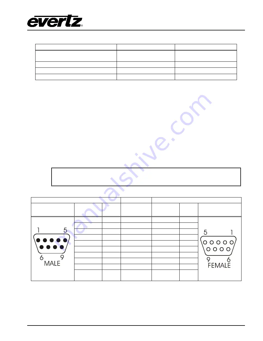
The 7825DSK2-LG(-HD)(-3G) is available with an optional temperature probe that is used to input data 
for display in a temperature logo.  Consult the temperature probe manual for information on installing 
the temperature probe.  Connect the temperature probe power adapter to the probe unit.  Connect the 
temperature probe to the 

COM  D 

or 

COM C 

connector on the 7825DSK2-LG(-HD)(-3G).  The 

temperature probe ships with an adapter cable to convert its RJ-45 conn

e

ctor to a standard 9 pin D 

connector. The RJ-45 plugs into the temperature probe.  You will need to create a straight-through 9 
pin male to female cable of the desired length according to the diagram in Table  2-6  to connect the 
probe to the 7825DSK2-LG(-HD)(-3G).  The serial port on the 7825DSK2-LG(-HD)(-3G)  must be set 
for RS-232 operation as described in section 2.1.3.   


The temperature probe cable should not exceed 1000 feet. 


7825DSK2-LG(-HD)(-3G) End 


Temperature Probe End 


9 pin D 

Male 

Pin 

Belden 

9729 

9 pin D 

Female 

Pin 


TxD 

-------1a------ 

RxD 

RxD 

-------1b------ 

TxD 


Rx Gnd 

Gnd 

---drain 1---- 

Gnd 


Frame 

Gnd 

Shield 

---drain 2---- 

Frame 

Gnd 

Shield 

Table 2-10: Temperature Probe Extender Cable 


Summary of Contents for 7825DSK2-LG-3G

Page 1: ...n 2 0 May 2017 The material contained in this manual consists of information that is the property of Evertz Microsystems and is intended solely for the use of purchasers of the 7825DSK2 LG Series Logo Inserter and Downstream Keyer Evertz Microsystems expressly prohibits the use of this manual for any purpose other than the operation of the device All rights reserved No part of this publication may...

Page 2: ...This page left intentionally blank ...

Page 3: ...grounding type plug has two blades and a third grounding prong The wide blade or the third prong is provided for your safety If the provided plug does not fit into your outlet consult an electrician for replacement of the obsolete outlet Protect the power cord from being walked on or pinched particularly at plugs convenience receptacles and the point where they exit from the apparatus Only use att...

Page 4: ...N TO USERS IN THE U S A NOTE FCC CLASS A DIGITAL DEVICE OR PERIPHERAL This equipment has been tested and found to comply with the limits for a Class A digital device pursuant to Part 15 of the FCC Rules These limits are designed to provide reasonable protection against harmful interference when the equipment is operated in a commercial environment This equipment generates uses and can radiate radi...

Page 5: ...t notes to EAS over TCP IP section Dec 2011 1 6 Updates made throughout section 5 Jan 2012 2 0 Full manual update May 2017 Information contained in this manual is believed to be accurate and reliable However Evertz assumes no responsibility for the use thereof nor for the rights of third parties which may be affected in any way by the use thereof Any representations in this document concerning per...

Page 6: ...ECTING THE VIDEO 2 7 2 5 1 Video Inputs 2 7 2 5 2 Video Outputs 2 7 2 5 3 Genlock Reference 2 7 2 6 CONNECTING THE LINEAR TIME CODE 2 8 2 7 CONNECTING TO AN ETHERNET NETWORK 2 8 2 8 CONNECTING THE GENERAL PURPOSE INPUTS AND OUTPUTS 2 9 2 9 CONNECTING THE OPTIONAL TEMPERATURE PROBE 2 13 2 10 MODULE CONFIGURATION 2 14 2 11 CONFIGURING THE MODULE USING THE MODULE SERIAL PORT 2 14 2 11 1 Network Confi...

Page 7: ... Timer 4 7 4 4 NETWORK TAB 4 8 4 4 1 Network IP Address 4 8 4 4 2 Sub Net Mask 4 8 4 4 3 Gateway 4 8 4 4 4 MAC Address 4 8 4 5 GENERAL TAB 4 8 4 5 1 Firmware Version 4 9 4 5 1 1 Monitoring the Build Number 4 9 4 5 1 2 Enabling Reboot 4 9 4 5 2 Port Entry 4 9 4 5 3 General 4 11 4 5 3 1 Automation Debug and M2100 Debug Functions 4 11 4 5 4 Controls 4 11 4 5 4 1 Monitoring the Genlock Status 4 11 4 5...

Page 8: ...1 EAS over TCP IP 4 22 4 11 1 1 Setting the EAS Vertical Position 4 23 4 11 1 2 Setting the EAS Font 4 23 4 11 1 3 Setting the EAS Height 4 23 4 11 1 4 Setting the EAS Rate 4 23 4 11 2 EAS Colour Settings 4 23 4 12 PRESETS TAB 4 24 4 13 MEDIA TAB 4 25 4 13 1 General Control 4 25 4 13 1 1 Setting the Control Bypass 4 25 4 13 2 Preview Channel 4 25 4 13 2 1 Setting the Video Input 4 25 4 13 2 2 Sett...

Page 9: ...Setting the Font Name 4 32 4 13 10 Setting the Crawl Logo Colours 4 32 4 13 10 1 Setting the Crawl Outline Opacity 4 33 4 13 10 2 Setting the Logo Layer 4 33 4 13 10 3 Logo Quick In Fade Out Effect 4 33 4 13 11 Selecting a Logo or Media Item and Issuing a Fade Cue Fade Out 4 33 4 13 12 Audio Clip Configuration Settings 4 34 4 13 13 Setting the Audio Clip Repeat Count 4 34 4 14 AUDIO CONTROL TAB 4 ...

Page 10: ...k 5 15 5 6 4 3 Setting Up the Gateway 5 16 5 6 4 4 Displaying the Ethernet Hardware Address 5 16 5 6 4 5 Setting Up the Primary and Secondary Servers 5 16 5 6 4 6 Setting Up the MCP IP Address 5 16 5 6 5 Displaying SNMP Trap Destination 5 16 5 6 6 Displaying AFD Logo Trigger 5 17 5 6 7 Setting the Serial Protocol for COM Ports D and E 5 17 5 6 8 Setting the Genlock Status 5 18 5 6 9 Protecting Lin...

Page 11: ... IP 5 35 5 14 2 Setting the Vertical Position of EAS Crawl Display 5 36 5 14 3 Setting the Font used for the EAS Crawl Display 5 36 5 14 4 Setting the Font Size for the EAS Crawl Display 5 36 5 14 5 Setting the Crawl Rate for the EAS Crawl Display 5 36 5 14 6 Setting the Colours for the EAS Crawl Display 5 37 5 15 MEDIA CONFIGURATION ITEMS 5 38 5 15 1 Setting the Logo Horizontal Position 5 39 5 15...

Page 12: ...eral Purpose Inputs and Outputs 8 2 8 1 7 Electrical 8 2 8 1 8 Physical 8 2 9 UPGRADING THE FIRMWARE 9 1 9 1 OVERVIEW 9 1 9 2 FIRMWARE UPGRADE VIA OVERTURE APPLICATION RECOMMENDED PROCEDURE 9 2 9 3 FIRMWARE UPGRADE VIA TERMINAL PROGRAM 9 3 9 3 1 Step 1 Transferring the File to the CF 9 3 9 3 1 1 Method 1 Using Overture 2 9 3 9 3 1 2 Method 2 Copy Using a CF Reader 9 4 9 3 2 Step 2 Serial Upgrade P...

Page 13: ...K Window 4 12 Figure 4 7 Matte Window 4 13 Figure 4 8 GPI GPO Control Window 4 15 Figure 4 9 Temperature Window 4 19 Figure 4 10 Transition Window 4 20 Figure 4 11 Wipe Pattern Angles 4 21 Figure 4 12 EAS Window 4 22 Figure 4 13 Presets Window 4 24 Figure 4 14 Media Window 4 25 Figure 4 15 Voice Over Control Options 4 26 Figure 4 16 Static Logo Configuration Settings 4 28 Figure 4 17 Crawl Logo Co...

Page 14: ...r Cable 2 6 Table 2 7 Video Input Formats 2 7 Table 2 8 Standard RJ45 Wiring Colour Codes 2 8 Table 2 9 GPIO Maximum Ratings 2 13 Table 2 10 Temperature Probe Extender Cable 2 13 Table 5 1 Top Level of the General Setup Menu 5 9 Table 5 2 Top Level of the Manage Files Setup Menu 5 21 Table 5 3 Top Level of the Matte Setup Menu 5 22 Table 5 4 Top Level of the DSK Setup Menu 5 24 Table 5 5 Top Level...

Page 15: ...800 Multiframe Manual 7825DSK2 LG HD 3G 3G HD SD Dual Downstream Keyer OVERVIEW Revision 2 0 CHAPTER 1 TABLE OF CONTENTS 1 OVERVIEW 1 1 1 1 SUMMARY 1 1 1 2 HOW TO USE THIS MANUAL 1 2 1 3 DEFINITIONS 1 3 ...

Page 16: ...7800 Multiframe Manual 7825DSK2 LG HD 3G 3G HD SD Dual Downstream Keyer Revision 2 0 OVERVIEW This page left intentionally blank ...

Page 17: ...DSK2 LG 3G are VistaLINK capable offering remote monitoring control and configuration capabilities via Simple Network Management Protocol SNMP This product feature offers another solution to manage operations including signal monitoring and module configuration from SNMP enabled control systems Manager or NMS locally or remotely Features Two downstream keyers with full preview Supports 525i 59 94 ...

Page 18: ...n Status Indicators VistaLINK PRO Front Panel Operation Remote Control Panel Operation Playlist Commands HTML Audio Setup Technical Description and Upgrading the Firmware The overview section contains a brief overview of the 7825DSK2 LG HD operations technical features and a glossary to define concepts and terms used throughout the remainder of the manual We highly recommend taking the time to bec...

Page 19: ...eferred to as the digital cliff This is a phenomenon found in digital video systems that describes the sudden deterioration of picture quality when due to excessive bit errors often caused by excessive cable lengths The digital signal will be perfect even though one of its signal parameters is approaching or passing the specified limits At a given moment however the parameter will reach a point wh...

Page 20: ...ted by a notification over a custom TCP IP port EAS Emergency Alert System a national warning system employed in the U S EBU European Broadcasting Union An organisation of European broadcasters that among other activities provides technical recommendations for the 625 50 line television systems Embedded audio Digital audio is multiplexed onto a serial digital video data stream ITU The United Natio...

Page 21: ...ards for the film and television industries SMPTE 12M The SMPTE standard for Time and address code SMPTE 12M defines the parameters required for both linear and vertical interval time codes SMPTE 125M The SMPTE standard for bit parallel digital interface for component video signals SMPTE 125M defines the parameters required to generate and distribute component video signals on a parallel interface...

Page 22: ...7800 Multiframe Manual 7825DSK2 LG HD 3G 3G HD SD Dual Downstream Keyer Page 1 6 Revision 2 0 OVERVIEW This page left intentionally blank ...

Page 23: ... 3 POWER REQUIREMENTS 2 6 2 4 CONNECTING THE REMOTE CONTROL PANEL 2 6 2 5 CONNECTING THE VIDEO 2 7 2 5 1 Video Inputs 2 7 2 5 2 Video Outputs 2 7 2 5 3 Genlock Reference 2 7 2 6 CONNECTING THE LINEAR TIME CODE 2 8 2 7 CONNECTING TO AN ETHERNET NETWORK 2 8 2 8 CONNECTING THE GENERAL PURPOSE INPUTS AND OUTPUTS 2 9 2 9 CONNECTING THE OPTIONAL TEMPERATURE PROBE 2 13 2 10 MODULE CONFIGURATION 2 14 2 11...

Page 24: ...Unit 2 12 Figure 2 6 Powering the General Purpose Output Opto Isolators from an External Power Supply 2 12 Figure 2 7 Tera Term Main Menu 2 15 Figure 2 8 Tera Term Network Configuration 2 16 Tables Table 2 1 Remote Panel Port Pin Definitions 2 2 Table 2 2 Serial Port C and D RS422 Pin Definitions 2 3 Table 2 3 Serial Port Pin Definitions 2 4 Table 2 4 GPI O Connector Pin Definitions 2 5 Table 2 5 ...

Page 25: ...1 to 2 1 5 describe the specific video audio and control signals that should be connected to the 7825DSK2 LG HD and 7825DSK2 LG 3G rear plates Sections 2 4 to 2 8 describe how to connect the module into your system Figure 2 1 7825DSK2 LG HD 7825DSK2 LG 3G Rear Panels 2 1 1 Video Connections PGM IN A This BNC connector is the program input A to the 7825DSK2 LG HD 3G PGM IN B This BNC connector is t...

Page 26: ...ohm terminated input is for connecting an analog video reference Connect the GENLOCK connector to the reference input sync The 7825DSK2 LG HD 3G can also be set to derive its timing from the input video connected to the PGM IN A input using the REFERENCE menu 2 1 3 Serial I O Connections A breakout cable Evertz Part WP SERIAL COM 1 0 is provided with each 7825DSK2 LG HD 3G This breakout cable conn...

Page 27: ... set for the RS 232 mode of operation the ports have the pinout shown in Table 2 5 When they are set for the RS 422 mode of operation the ports have the pinout shown in Table 2 2 The RS 422 pinout for the SERIAL CONTROL and COM D ports is not a standard SMPTE RS422 pinout You will have to make a custom cable in order to use these ports in the RS422 configuration Pin Name Description 1 GND Chassis ...

Page 28: ... 11 RTS Comm Port D Request To Send 12 Rx Comm Port D Receive Data 13 Tx Comm Port D Transmit Data 14 CTS Comm Port D Clear To Send 15 LTC Local Time Code Table 2 3 Serial Port Pin Definitions 2 1 4 GPI O Connections GPI O This 15 pin female high density D connector AUX I O contains several general purpose control inputs and outputs The inputs are used to connect manual or automatic triggers for t...

Page 29: ...uts2 Table 2 4 GPI O Connector Pin Definitions Pin Name Description 1 GND Chassis ground 2 TxD RS 232 Transmit Output 3 RxD RS 232 Receive Input 4 5 Sig Gnd RS 232 Signal Ground 6 7 RTS RS 232 RTS Input 8 CTS RS 232 CTS Output 9 Table 2 5 Serial Port C and D RS232 Pin Definitions 2 1 5 Ethernet Network Connections ETHERNET This RJ 45 connector is an Ethernet port used for high speed firmware upgra...

Page 30: ...and an EMI line filter CAUTION TO REDUCE THE RISK OF ELECTRICAL SHOCK GROUNDING OF THE GROUND PIN OF THE MAINS PLUG MUST BE MAINTAINED 2 4 CONNECTING THE REMOTE CONTROL PANEL The 7825DSK2 LG HD 3G is available with a rack mountable remote control panel The remote control panel is connected to the SERIAL CONTROL connector on the Keyer units using COM B of the breakout cable Evertz Part WP SERIAL CO...

Page 31: ...5M NTSC 625i 50 720 x 576 25 I EBU TECH 3267 E PAL 720p 50 1280 x 720 25 P SMPTE 296M PAL 720p 59 94 1280 x 720 59 94 60 1 001 P SMPTE 296M NTSC 1080i 50 1920 x 1080 25 I SMPTE 274M PAL 1080i 59 94 1920 x 1080 29 97 30 1 001 I SMPTE 274M NTSC 1080p 59 94 1920 x 1080 59 94 P SMPTE 274M NTSC 1080p 50 1920 x 1080 50 P SMPTE 274M PAL Table 2 7 Video Input Formats 2 5 2 Video Outputs The PROG OUT outpu...

Page 32: ... using the pinout information in Table 2 8 A colour code wiring table is provided in Table 2 8 for the current RJ 45 standards AT T 258A or EIA TIA 258B colour coding shown Also refer to the notes following the table for additional wiring guide information Pin 1 Pin Signal EIA TIA 568A AT T 258A or EIA TIA 568B 10BaseT or 100BaseT 1 Transmit White Green White Orange X 2 Transmit Green White or Whi...

Page 33: ... no valid connection 2 8 CONNECTING THE GENERAL PURPOSE INPUTS AND OUTPUTS Figure 2 2 shows a simplified schematic diagram of the GPIO circuitry The user can connect GP 3 3V supplied from the keyer unit into the Vext pin to provide power to the GPIO opto isolator circuitry In this configuration the user can activate GPIs simply by connecting the GPI input pins to Ground see Figure 2 3 This can be ...

Page 34: ...located preset definition The 8 GPIs A through H are dedicated as load logo controls When one of these GPI inputs is activated the corresponding logo is loaded into active video If multiple inputs are active both commands are ignored until a single input is recognized The GPI to logo allocation is programmable using the GPI Setup menu item on the PRESET menu See section 5 11 5 See section 4 12 of ...

Page 35: ...D 3G 3G HD SD Dual Downstream Keyer INSTALLATION Revision 2 0 Page 2 11 Figure 2 3 Powering the General Purpose Input Opto Isolators from the Unit Figure 2 4 Powering the General Purpose Input Opto Isolators from an External Power Supply ...

Page 36: ... 3G 3G HD SD Dual Downstream Keyer Page 2 12 Revision 2 0 INSTALLATION Figure 2 5 Powering the General Purpose Output Opto Isolators from the Unit Figure 2 6 Powering the General Purpose Output Opto Isolators from an External Power Supply ...

Page 37: ...ure probe Connect the temperature probe power adapter to the probe unit Connect the temperature probe to the COM D or COM C connector on the 7825DSK2 LG HD 3G The temperature probe ships with an adapter cable to convert its RJ 45 connector to a standard 9 pin D connector The RJ 45 plugs into the temperature probe You will need to create a straight through 9 pin male to female cable of the desired ...

Page 38: ...r can be used to connect to the 7825DSK2 LG HD 3G to configure some of the audio and time parameters This interface does not require any additional software to be installed just web browser software Overture Allows the user to manage and control the media on the 7825DSK2 LG HD 3G 2 11 CONFIGURING THE MODULE USING THE CARD EDGE SERIAL PORT 1 Through the card edge s serial port and using the serial ...

Page 39: ... Revision 2 0 Page 2 15 Figure 2 7 Tera Term Main Menu 2 11 1 Network Configuration 4 To open a menu item type the corresponding number from the list and then press ENTER Select option 1 Network Configuration from the Main Menu to set the IP parameters for the 7825DSK2 LG HD 3G module ...

Page 40: ... or 6 when a change has been made before exiting the menu In the above menu Figure 2 8 selecting options 1 through 4 allows the user to set the networking parameters of the 7825DSK2 LG HD 3G 6 Once changes are completed and saved the 7825DSK2 LG HD 3G module should be power cycled for the changes to take effect Once networked further configuration is performed using VLPro or the RCP Warning Do not...

Page 41: ...CP users can router ANY input source to the PGM IN A PGM IN B FILL IN 1 2 and KEY IN 1 2 The communication between the Xenon and 7825DSK2 LG HD 3G is done over a serial cable If multiple 7825DSK2 LG HD 3G s are to be connected to a single Xenon router then a 7700R SC will be required to bridge the serial connections to the single router Please call the factory for more information on this configur...

Page 42: ...7800 Multiframe Manual 7825DSK2 LG HD 3G 3G HD SD Dual Downstream Keyer Page 2 18 Revision 2 0 INSTALLATION This page left intentionally blank ...

Page 43: ...7800 Multiframe Manual 7825DSK2 LG HD 3G 3G HD SD Dual Downstream Keyer STATUS INDICATORS Revision 2 0 CHAPTER 3 TABLE OF CONTENTS 3 STATUS INDICATORS 3 1 Figures Figure 3 1 Status LED Locations 3 1 ...

Page 44: ...7800 Multiframe Manual 7825DSK2 LG HD 3G 3G HD SD Dual Downstream Keyer Revision 2 0 STATUS INDICATORS This page left intentionally blank ...

Page 45: ...OCAL STATUS This Green and Red LED indicates poor module health and will be ON if a local input power fault exists i e a blown fuse The LOCAL FAULT indication can also be reported to the frame through the FRAME STATUS jumper The status will toggle between Green status is good or Red status is not good FPGA STATUS This Green LED indicates good module health It will be ON when the module has NOT boo...

Page 46: ...7800 Multiframe Manual 7825DSK2 LG HD 3G 3G HD SD Dual Downstream Keyer Page 3 2 Revision 2 0 STATUS INDICATORS This page left intentionally blank ...

Page 47: ... 6 4 3 8 Selecting Whether the Time Code Input is UTC or Local Time 4 6 4 3 9 Setting the LTC Date Format 4 6 4 3 10 LTC Presence Detection Enabled 4 6 4 3 11 Synchronizing the Real Time Clock to the UTC Time 4 7 4 3 12 Setting the Time Zone Offset 4 7 4 3 13 Up Down Timer 4 7 4 3 13 1 Setting the Up Down Timer 4 7 4 4 NETWORK TAB 4 8 4 4 1 Network IP Address 4 8 4 4 2 Sub Net Mask 4 8 4 4 3 Gatew...

Page 48: ... TAB 4 19 4 9 1 Setting the Temperature Format 4 19 4 9 2 Setting the Temperature Source 4 19 4 9 3 Setting the Static Temperature 4 20 4 9 4 Temperature Read Loss 4 20 4 10 TRANSITION TAB 4 20 4 10 1 Setting the Transition Type 4 20 4 10 2 Setting the Transition Rate 4 21 4 10 3 Setting the Transition Swap Mode 4 21 4 10 4 Pausing a Transition 4 21 4 10 5 Setting Program Bus Change 4 22 4 11 EAS ...

Page 49: ...he Crawl Logo Vertical Position 4 30 4 13 9 3 Setting the Crawl Logo Transparency Gain 4 30 4 13 9 4 Setting the Crawl Logo Fade In Duration 4 31 4 13 9 5 Setting the Crawl Logo Display Time Hold 4 31 4 13 9 6 Setting the Crawl Logo Fade Out Duration 4 31 4 13 9 7 Setting the Up Down Timer 4 31 4 13 9 8 Setting the Crawl Rate 4 31 4 13 9 9 Setting the Crawl Repeats Count 4 31 4 13 9 10 Setting the...

Page 50: ...dow 4 15 Figure 4 9 Temperature Window 4 19 Figure 4 10 Transition Window 4 20 Figure 4 11 Wipe Pattern Angles 4 21 Figure 4 12 EAS Window 4 22 Figure 4 13 Presets Window 4 24 Figure 4 14 Media Window 4 25 Figure 4 15 Voice Over Control Options 4 26 Figure 4 16 Static Logo Configuration Settings 4 28 Figure 4 17 Crawl Logo Configuration Settings 4 30 Figure 4 18 Choose a Colour Dialog Box 4 32 Fig...

Page 51: ...y VistaLINK enables the user to configure devices in the network from a central station and receive feedback that the configuration has been carried out There are 3 components of SNMP 1 An SNMP manager also known as a Network Management System NMS is a computer running special software that communicates with the devices in the network Evertz VistaLINK Pro Manager graphical user interface GUI third...

Page 52: ... 525i 59 94 for operation with 4 x 3 aspect ratio 525i 59 94 video conforming to SMPTE 125M 16x9 525i Select 16x9 525i for operation with 16 x 9 aspect ratio 525i video conforming to SMPTE 125M 625i 50 Select 625i 50 for operation with 4 x 3 aspect ratio 625i 50 video conforming to EBU TECH 3267 E 720p 50 Select 720p 50 for operation with 720p 50 video conforming to SMPTE 296M 720p 59 94 Select 72...

Page 53: ...le increments In order to advance the horizontal timing of the output video with respect to the genlock video set the control to the maximum number of samples per line for the output video standard minus the number of samples that you wish to advance the output video i e for 1080i 59 94 output video the total number of samples per line is 2200 so to advance the output video 5 samples set the value...

Page 54: ...ory Input Parameters When an Input is set to YES the Output will become muted no video if the Input becomes invalid or is absent regardless of whether or not that Input is currently selected to be routed to the Output 4 3 TIME TAB The Time tab enables the user to set the time settings for the 7825DSK2 LG HD 3G Figure 4 3 Time Window ...

Page 55: ...rsal Coordinated Time UTC but can also be adjusted for time zone offsets from UTC and for daylight saving time and displayed as local time Local 4 3 2 Displaying the Universal Time Clock Time This option is used to display the UTC time clock The time displays are always shown in the 24 hour time format 4 3 3 Displaying the Local Time This option is used to display the clock time as local time UTC ...

Page 56: ...the Time Code Input is UTC or Local Time This option allows the user to select whether incoming time code will be in UTC or local time This information is necessary to correctly update the RTC clock from the time code Select Local when the incoming LTC is local time Select UTC when the incoming LTC is Universal Coordinated time 4 3 9 Setting the LTC Date Format This option is used to select the fo...

Page 57: ...s time zone offset will be added to the UTC time along with the Daylight Saving time correction to obtain the Local time Time zones are normally in one hour or 30 minute increments and can be or from UTC Time zones east of Greenwich are and time zones west of Greenwich are 4 3 13 Up Down Timer 4 3 13 1 Setting the Up Down Timer This item lets you configure the behaviour of Timer 1 and Timer 2 Cloc...

Page 58: ...ess of the 7825DSK2 LG HD 3G within the network 192 168 1 XXX is an example of an IP address in a private internal network 4 4 2 Sub Net Mask This option displays the subnet mask of the network Specifically this parameter outlines all the IP addresses that can communicate with the 7825DSK2 LG HD 3G 4 4 3 Gateway This option identifies the IP address of the gateway commonly referred to as the firew...

Page 59: ... unit Once selected a message will appear in order to confirm whether the user would like to proceed with the reboot 4 5 2 Port Entry The menu items for Serial Control COM D and COM E are the same For simplicity only the COM D menu items will be shown in the manual The following items are available in the drop down menu Serial Control Configures the function of the SERIAL CONTROL COM C Port COM D ...

Page 60: ...rol Panel when you want to enable the RCP in addition to VLPro based access this is generally not necessary if you are using VLPro to configure the card Plug the breakout cable marked COM PORT B to the back of the RCP Select Console to view the system console output There are three settings that are used when the 7825DSK2 LG HD 3G is under automation control See your automation vendor for informat...

Page 61: ...ebug Select Automation Debug when you want to control the 7825DSK2 LG HD 3G using the Evertz automation protocol This setting should be used when you are controlling the 7825DSK2 LG HD 3G from the Evertz MetaCast 2 software M2100 Debug Select M2100 Debug when you want to control the 7825DSK2 LG HD 3G using the Grass Valley M2100 7825DSK2 LG HD 3G automation protocol Keyer Type This field the curre...

Page 62: ...2 LG HD 3G has a downstream keyer layer that allows the user to key objects into the output video The DSK Setup window is used to configure the downstream keyer functions key type gain and thresholds Figure 4 6 DSK Window The DSK tab has two parts DSK and DSK 2 Both of these items have the same parameters therefore the descriptions below apply to both DSK parts 4 6 1 1 Setting the Key Type This op...

Page 63: ...n is used to modify the threshold value used in Self Key mode The Self Key is a hard key based on the luminance value of the fill signal applied to the FILL video input All luminance values that are above the Key Threshold will be keyed from the Fill signal All values from the key that fall below the Key Threshold will be keyed from the background video The default value for the Key Threshold is 4...

Page 64: ... turn off the black matte overlay 4 7 2 Setting a User Defined Matte Aspect Ratio There are two options that allow the user to define custom aspect ratios for the matte Selecting a pre defined aspect ratios will lose any changes you have made to the Matte Top and Matte Bottom options unless they are stored using the user presets see section 4 12 When you manually change the Matte Top and Matte Bot...

Page 65: ... aspect ratios available When you select one of these aspect ratios the 7825DSK2 LG HD 3G will automatically set the Matte Top and Matte Bottom menu items In addition you can set a user defined aspect ratio by manually changing the Matte Top and Matte Bottom menu items See section 4 7 2 4 8 GPI GPO CONTROL TAB The GPI GPO Control enables the user to configure the General Purpose Inputs and Outputs...

Page 66: ...d Video A C Inv Select Video A C Inv to indicate that the signal is not present Voice Over Select Voice Over to activate the output when the voiceover on the program output bus is active Media and Logo Status Select Media and Logo Status to make the GPO low when the media layer is turned on and a logo is being keyed on the Program bus Media Status Select Media Status to make the GPO low when the m...

Page 67: ...st scripts can be configured in the Playlist Editor For the purposes of GPI configuration a playlist script is considered to be a logo you can associate a GPI action with a playlist script explicitly in the GPI configuration menu again providing there is no gpi script file present to override the GPI configuration The GPI script files are text files therefore they can be easily edited in notepad T...

Page 68: ...go will not be displayed by this action IN Select IN to load the logo selected by the CLogo menu item into memory and fade it in OUT Select OUT to fade out the logo selected by the CLogo menu item TOGGLE Select TOGGLE when the GPI is closed DUCK IN Select DUCK IN to begin a Duck Audio Insert DUCK OUT Select DUCK OUT to end a Duck Audio Insert DUCK Select DUCK to toggle the state of the Duck Audio ...

Page 69: ...lsius Note This option is only used when the Temperature Source option is set to Manual When you create a temperature logo you select the format as well If for example you have created a temperature logo that is formatted for Celsius and you manually set the temperature in degrees Fahrenheit the 7825DSK2 LG HD 3G will automatically convert the value to degrees Celsius so that the correct value is ...

Page 70: ...on types The TRANSITION setup window is used to configure the transition type rate pause and swap mode Figure 4 10 Transition Window 4 10 1 Setting the Transition Type This option is used to select the type of transition you would like applied when the DO TRANSITION button is pressed See section 4 13 5 Transition effects only appear on the program output bus Transitions on the preview output bus a...

Page 71: ...hen set to Swap the input video and audio of the Preview Bus and the Program Bus will be swapped at the end of the transition Logos and other media being keyed on the respective buses will also be swapped with the inputs When set to No Swap the input video and audio of the Preview Bus will be transferred to the Program Bus transition Logos and other media being keyed on the Preview Bus will also b...

Page 72: ...es to insert as crawls and WAV files to play as audio clips Refer to the HTML section 7 to configure the playback of the EAS audio EAS over TCP IP EAS over Ethernet is supported with Trilithic s EASy Plus box For further details refer to the step by step instructions in the Trilithic EASyPlus Setup Tech Note EAS over TCP IP is also supported by the Dasdec device For further details refer to Dasdec...

Page 73: ...ting the EAS Height The EAS Height option is used to set the font size that will be used for the EAS scrolling text message The EAS height is the vertical size of the font measured in lines of video 4 11 1 4 Setting the EAS Rate The EAS Rate option is used to set the speed with which the scrolling text moves from right to left across the screen measured in samples per field The default is 16 0 sam...

Page 74: ...ed to store and recall user presets After upgrading the 7825DSK2 LG HD 3G with new firmware all presets should be recalled using the Recall Preset menu item the values for new features must be set and the preset must be saved again using the Store Preset menu item IF THIS IS NOT DONE OLD PRESETS COULD BE RECALLED WITH UNDESIRABLE SETTINGS Figure 4 13 Presets Window PRESET Using the drop down menu ...

Page 75: ...w 4 13 1 General Control 4 13 1 1 Setting the Control Bypass The Control Bypass option controls the bypass relay When the Don t Bypass option is selected the unit will run in normal operating mode When the Bypass option is selected the unit will run in bypass mode 4 13 2 Preview Channel 4 13 2 1 Setting the Video Input The Video Input section allows the user to select one of the following three so...

Page 76: ...1 Setting the Video Input The Video Input control allows the user to select one of the following three video inputs Source A Source B or Black internal black video generator as the source for the program video bus 4 13 3 2 Setting the DSK Layer The DSK Layer allows the user to enable or disable the downstream keyer layer for the Program Bus 4 13 3 3 Setting the Logo Layer The Logo Layer control al...

Page 77: ...r automation control Within the Transition window when the Transition Swap Mode is set to Swap the input video and audio of the Preview Bus and the Program Bus will be swapped at the end of the transition Logos and other media being keyed on the respective buses will also be swapped with the inputs When the Transition Swap Mode is set to No Swap the input video and audio of the Preview Bus will be...

Page 78: ...standard in use 4 13 8 3 Setting the Logo Transparency Gain This option is used to adjust the opacity the inverse of transparency of the logo as a percentage of the original opacity when the logo was created When the Gain value is set at its default value of 100 the logo will be displayed at its original opacity For example if the logo is created at 10 opaque adjusting the Gain value to 200 will r...

Page 79: ...Timer selects 1 of the 2 timers for the selected media The default for the UD Timer is NONE Note The Up Down Timer is only used for time objects 4 13 9 Crawl Logo Configuration Settings When the Crawl CLH option is added to the 7825DSK2 LG HD 3G it has the ability to key scrolling text messages over the program video In order to set up the crawl logo and enter the text from the crawl logo you will...

Page 80: ...ontal crawls The position is referenced to the top edge of the logo The range of values depends on video standard in use 4 13 9 3 Setting the Crawl Logo Transparency Gain This option is used to adjust the opacity the inverse of transparency of the logo as a percentage of the original opacity when the logo was created When the Gain value is set at its default value of 100 the logo will be displayed...

Page 81: ...ption is used to set the speed with which the scrolling text moves from right to left across the screen measured in seconds per screen For example it will take 8 seconds for the text to scroll across a screen with a scroll rate of 8 This default value of 8 should provide a comfortable rate however should you change the size of the font you should also adjust the scrolling speed 4 13 9 9 Setting th...

Page 82: ...o set the font that will be used for the crawl logo scrolling text message 4 13 10 Setting the Crawl Logo Colours There are two menu items used to set the text foreground and background colours of the crawl logo For the sake of simplicity only the menu item for setting the background colour will be described in the manual The Crawl FG in RGB Format is set the same way The Crawl BG in RGB Format op...

Page 83: ...lowing fade in fade out effects Fade Wipe t b top to bottom Push r l Wipe l r left to right Wipe b t bottom to top Push t b Wipe r l right to left Push l r Push b t 4 13 11 Selecting a Logo or Media Item and Issuing a Fade Cue Fade Out Figure 4 19 Issuing a In Out Cued Upon selecting a logo or media item under the Name column the user can click on the Status column adjacent to the desired logo and...

Page 84: ...2 LG HD 3G has the ability to insert audio clips into the program audio path These clips can be played by themselves or associated with logos in a playlist Figure 4 21 Audio Clip Configuration Settings 4 13 13 Setting the Audio Clip Repeat Count This menu item is used to set the number of times the audio clip will play If you set the Repeat control to 0 the audio clip will play continuously Otherw...

Page 85: ...y accessible via automation commands BKG A This column configures the background audio that is used when 7825DSK2 LG HD 3G is passing the video which is connected to the INPUT BNC connector FILL B This column configures the fill audio that is used when the 7825DSK2 LG HD 3G is passing the video which is connected to the INPUT BNC connector AUDIO KEYER The gain settings boost the associated input a...

Page 86: ...as a wav file and played as a normal audio clip VOICEOVER This column is used to configure the input source which is to be used for voice overs as well as the output channel s which the voice over audio is to be inserted into You can also specify the desired mix levels for voiceovers here 4 14 2 Settings SOURCE Specifies the input source for the output audio channel The following is a description ...

Page 87: ...video BEMB4L group 2 channel 3 of embedded audio on the input video BEMB4R group 2 channel 4 of embedded audio on the input video BEMB5L group 3 channel 1 of embedded audio on the input video BEMB5R group 3 channel 2 of embedded audio on the input video BEMB6L group 3 channel 3 of embedded audio on the input video BEMB6R group 3 channel 4 of embedded audio on the input video BEMB7L group 4 channel...

Page 88: ...d the duck affects the active layer of the Black Bkg Fill Audio Keyer layer The setting above provides for the audio clips in play mode to output on all audio channels the audio is mixed with the left and right channels of the pre recorded audio clip The left and right channels are then mixed with all the output audio channels The audioclip layer must be configured in order to hear audio clips on ...

Page 89: ... 6 2 Setting the Video Output Timing With Respect To Reference 5 11 5 6 3 Configuring the Real Time Clock 5 12 5 6 3 1 Displaying the Local Time 5 12 5 6 3 2 Displaying the UTC Time 5 12 5 6 3 3 Setting the Real Time Clock 5 12 5 6 3 4 Setting the Time Zone Offset 5 13 5 6 3 5 Enabling Daylight Saving Time Compensation 5 13 5 6 3 6 Selecting Whether the Time Code input is UTC or Local Time 5 14 5 ...

Page 90: ...ng the Transition Type 5 26 5 10 2 Setting the Transition Rate 5 26 5 10 3 Setting the Transition Swap Mode 5 27 5 10 4 Pausing a Transition 5 27 5 10 5 Setting Program Bus Change 5 27 5 11 PRESET CONFIGURATION ITEMS 5 27 5 11 1 Configuring the GPI Inputs 5 28 5 11 1 1 Selecting One of the GPI Inputs to Configure 5 29 5 11 1 2 Configuring the GPI Actions 5 29 5 11 2 Configuring the GPO Outputs 5 3...

Page 91: ...the Crawl Logo Text Font Size 5 41 5 15 8 5 Setting the Crawl Logo Text Font 5 41 5 15 8 6 Setting the Crawl Logo Transparency 5 41 5 15 8 7 Setting the Crawl Logo Colours 5 42 5 15 9 Audio Clip Configuration Items 5 42 5 15 9 1 Setting the Audio Clip Repeat Count 5 42 5 15 9 2 Audio Clip Configuration 5 42 Figures Figure 5 1 7825DSK2 LG HD 3G Front Remote Control Panel Layout 5 1 Figure 5 2 7825D...

Page 92: ...7800 Multiframe Manual 7825DSK2 LG HD 3G 3G HD SD Dual Downstream Keyer Revision 2 0 RCP OPERATION This page left intentionally blank ...

Page 93: ...3G Please note that buttons of the 7725DSK RCP have been remapped to allow it to control the 7825DSK2 LG HD 3G As such some of the functionality of the buttons are changed or removed 5 1 AN OVERVIEW OF KEY AND DISPLAY FUNCTIONS Figure 5 1 7825DSK2 LG HD 3G Front Remote Control Panel Layout Figure 5 2 7825DSK2 LG HD 3G Back Remote Control Panel Layout The remote control panel consists of a 16 digit...

Page 94: ...voiceover layer for the audio Logos cannot be displayed when the media key layer is off If the LED is not illuminated then the media key layer is not active If the button LED is ON then the media key layer is enabled on the preview output bus 5 1 2 Program Bus Button Group A This button selects the video from the PGM IN A input for the program video output bus B This button selects the video from ...

Page 95: ... controls so that changes cannot be made to the program output bus The PGM BUS LOCK LED will turn ON indicating that the front panel PROGRAM BUS buttons are disabled When any of these buttons are pressed the front panel display will show the message Pgm Bus Locked for a few seconds Pressing the PGM BUS LOCK button again will return the front panel keys to their normal functions and the LED key wil...

Page 96: ...or menu choices at the bottom level of the menu system When not in the Setup menu the and arrow keys are used to select a logo to display 5 1 5 Control Panel Status Indicators 5 1 5 1 Preview Bus Status Indicators A This LED indicates that the PGM IN A video input is selected as the source for the preview video bus B This LED indicates that the PGM IN B video input is selected as the source for th...

Page 97: ... flashing When it is OFF it indicates that the downstream keyer layers are disabled on both buses COMM This LED is used to signal two types of communication to the 7825DSK2 LG HD 3G Flashing ON approximately every 1 5 seconds indicates that the control panel is communicating with the main microprocessor in the unit When the 7825DSK2 LG HD 3G is under automation control or logos or other media file...

Page 98: ... system 5 4 NAVIGATING THE SETUP MENU To enter the Setup menu press the SETUP button This will bring you to the main Setup menu where you can use the buttons to move up and down the list of available sub menus Once you have chosen the desired sub menu press the SELECT button to select the next menu level Once in a sub menu there may be another menu layer or there may be a list of parameters to adj...

Page 99: ...ype Transition Rate Transition Swap Transition Pause Program Bus Change PRESET Recall Preset Store Preset Export Preset Preset Source GPI Setup GPI Cload Prest Ctransition Caction Clogo Oload Prest Otransition Oaction Ologo GPO Setup GPO A GPO B GPO C GPO D AUDIO OVER TRANS VO In Rate VO Out Rate TEMPERATURE Temp Source Temp Format Set Temperature Temp Read Loss EAS Type Vert Pos n Font Font Heigh...

Page 100: ...address time and other miscellaneous settings and to update firmware MANAGE FILES This is used to set up various items related to moving and managing logo files MATTE This menu is used to configure the black overlay matte attributes DSK This menu is used to configure the DSK functions key type gain and thresholds DSK2 This menu is used to configure the DSK2 functions key type gain and thresholds T...

Page 101: ...me clock and LTC timecode input Network Info Configures the Ethernet Network Address for FTP uploads MCP Setup Configures the EMC DCP to be used as a control panel SNMP Trap Dest Configures the IP address for SNMP Traps AFD Triggers Configures the handling of AFD triggers Serial Control Configures the function of the SERIAL CONTROL COM C Port COM D Configures the function of the COM D serial port ...

Page 102: ...A video conforming to SMPTE 425M Select 1080i 50 for operation with 1080i 50 video conforming to SMPTE 274M Select 1080p 50 B for operation with 1080p 50 B video conforming to SMPTE 425M Select 1080p 50 A for operation with 1080p 50 A video conforming to SMPTE 425M Select 1080p 23 98 for operation with 1080p 23 98 video conforming to SMPTE 274M Select 1080p 23 98sF for operation with 1080p 23 98sF...

Page 103: ...em allows you to set the horizontal timing of the output video with respect to the genlock reference input Setting this control to 0 keeps the output video in time with the genlock reference Increasing the value will delay the output video in one sample increments In order to advance the horizontal timing of the output video with respect to the genlock video set the control to the maximum number o...

Page 104: ...ng the Local Time GENERAL This menu item is used to display the clock time as local time UTC time adjusted for the time zone offset and DST adjustment The time displays are always shown in the 24 hour time format Time Setup Local 12 34 50 5 6 3 2 Displaying the UTC Time GENERAL This menu item is used to display the UTC time clock The time displays are always shown in the 24 hour time format Time S...

Page 105: ...the hours values show a negative sign Then press the SELECT button and the minutes digits will begin flashing to indicate that they are in entry mode Set the minutes and seconds in the same way When you have entered the correct time press the SELECT button to the set the time zone offset The seconds digits will stop flashing to indicate that the time zone offset has been set Time Setup Zone 00 00 ...

Page 106: ...nt panel display will show RTC JAMMED for 1 second after the time has been synchronized Time Setup Jam RTC from UTC SELECT Confirm 5 6 3 8 Displaying the Local Date GENERAL This menu item is used to display the local date which is the UTC date adjusted by the time zone in yy mm dd format Time Setup LDate 00 12 30 5 6 3 9 Displaying the UTC Date GENERAL This menu item is used to display the UTC dat...

Page 107: ...the front panel display indicated by the letter on the left side of the display The left group of digits will be flashing to indicate that they are in entry mode Use the or buttons to change this group to the desired value Then press the SELECT button and the next group of digits will be flashing to indicate that they are in entry mode Set the remaining groups of digits in the same way When you ha...

Page 108: ...cal network This is a standard network administration construct The P option is for setting the IP address of the Primary Name Server P and the S option is setting for the Secondary Name Server S Network Info P 0 0 0 0 S 0 0 0 0 The Primary and Secondary server controls are optional and setting an IP address of 0 0 0 0 would disable it Please note that they are optional because only a limited numb...

Page 109: ...ned on when a trigger is received This feature is only available on HD units AFD Trigger Mode DSK Mode Logo 5 6 7 Setting the Serial Protocol for COM Ports D and E The three serial ports COM C D and E and the breakout cable for the 7825DSK2 LG HD 3G are used for various functions The SERIAL CONTROL COM C port and COM D ports are programmable and can be used for a variety of functions The menu item...

Page 110: ...trol the 7825DSK2 LG HD 3G using the Evertz automation protocol This is the setting you should use when you are controlling the 7825DSK2 LG HD 3G from the Evertz MetaCast 2 software Select M2100 AUTO when you want to control the 7825DSK2 LG HD 3G using the Grass Valley M2100 7825DSK2 LG HD 3G automation protocol Select XY AUTO when you want to control the 7825DSK2 LG HD 3G using the xy logo insert...

Page 111: ...o Timer2 then press the SELECT button again Up Down Timer Timer Timer1 Timer Timer2 GENERAL This menu item sets the hours for the timer It can be set to values from 0 to 23 hours To change the value press the SELECT button then use the or pushbuttons to change the hours for the timer Pressing SELECT again will set the value Up Down Timer Hour 0 GENERAL This menu item sets the minutes for the timer...

Page 112: ... Debug press the SELECT button and then use the or pushbuttons to scroll through the options Pressing the SELECT button gain will set the value Auto Proto Debug M2100 Auto Debug XY Auto Debug Evertz Auto Debu GENERAL This menu item turns the EAS Debug ON or OFF OFF is selected by default To enable Debug press the SELECT button and then use the or pushbuttons to scroll through the options Pressing ...

Page 113: ...rmat Erases the Destination media Table 5 2 Top Level of the Manage Files Setup Menu 5 7 1 Selecting the Source Media MANAGE FILES This menu item is used to select the source media drive that you are working with Each media drive is identified by the serial number of the compact flash media that is currently in the drive Units that are not fitted with one of the compact flash expansion drives will...

Page 114: ...his menu item is used to delete all the files from the source media chosen by the Media menu item Press the SELECT button to initiate the format function If there are active files on the media e g one or more of the logo files are being keyed the format function will fail Format Warning this function is not recommended but is provided as last resort The FORMAT function will completely remove all M...

Page 115: ...ratio by manually changing the Matte Top and Matte Bottom menu items See section 5 8 3 Please note that aspect 1 33 is only available when the unit is in SD video mode Aspect user aspect 1 33 aspect 1 77 aspect 1 85 aspect 2 35 aspect user 5 8 3 Setting a User Defined Matte Aspect Ratio There are two menu items that allow the user to define custom aspect ratios for the matte Selecting a pre define...

Page 116: ...y will occur Auto Key Enable Selects whether automation can turn the Media layer ON and OFF Table 5 4 Top Level of the DSK Setup Menu 5 9 1 Setting the Downstream Key Type DSK This menu item is used to select whether the downstream keyer will use the key and fill input to perform the keying function or whether it will perform a self key Select input to use the key and fill inputs provided on the K...

Page 117: ...ms do not create a distinction between the Media layer used for keying logos and the Downstream Keyer layers This control is provided to prevent the automation from turning the Media layer on and off at the same time as the DSK layers Verify the functionality of your automation system before changing this menu item Auto Key Enable Ctrl media yes Ctrl media no Please note that the Auto Key Enable c...

Page 118: ...For example a Wipe 45 transition will start a 45 degree wipe that will progress from the top left of the screen to the bottom right of the screen Transition Type Type Fade Type Cut Type Fade Cut Type Fade Fade Type Cut Fade Type Diamond Ou Type Diamond In Type Circle Out Type Cirlce In Type Box Out Type Box In Type TB Split Type LR Split Type TB Curtain Type LR Curtain Type TR Box Type TL Box Type...

Page 119: ...ot cut on the program bus For instance rather than selecting the next source on the Preset bus and then executing a transition the next source will out directly onto the Program bus When set to Clean the audio and video transition will be a clean smooth action When set to Hard the audio and video transition will be a hard abrupt action Program Bus Change Switch Clean Switch Hard 5 11 PRESET CONFIG...

Page 120: ...eneral purpose inputs GPIs that can be configured to trigger 2 different actions On Closure and On Open For example the On Closure event can be used to load a preset and perform a transition to the Program Bus The On Open event for the same GPI can be used to load a different user preset and perform a transition to the Program Bus For each event you can configure a preset to load transition to per...

Page 121: ...ns when the selected GPI closes CTransition CLoad CAction and CLogo There are also 4 menu items that configure the actions when the selected GPI opens OTransition OLoad OAction and OLogo For the sake of brevity only the On Close event menu items will be shown The applicable GPI is shown on the left of the front panel display Each GPI can be independently configured by first selecting the GPI using...

Page 122: ...be stopped or if a Duck Audio Insert is not in effect it will be started This function is useful if you want to use a momentary contact closure as opposed to a maintained contact closure to trigger a voice over but the disadvantage is that the current state of the voice over is not guaranteed Select All Out to fade out all logos Select TIMER1 or TIMER2 to initiate a count up or countdown function ...

Page 123: ...hen the voiceover on the program output bus is active Select Logo Medi to make the GPO low when the media layer is turned on and a logo is being keyed on the Program bus Select Media Sta to make the GPO low when the media layer is turned on for the Program bus Select Logo Stat to activate the output when the media key layer on the program output bus is active Select DSK Statu to activate the outpu...

Page 124: ...tion Store Preset Store 1 5 11 5 Exporting a User Preset PRESET This menu item is used to send the settings to 1 of the 10 user presets to the console serial port UPGRADE 232 as ASCII text This function is useful in archiving the settings of the presets or for diagnostic purposes Use the or buttons to select the preset that you want to export When you press the SELECT button the settings will be s...

Page 125: ...lowing section provides detailed information about each of the sub menu items Temperature Source Configures the source of the temperature Temperature Format Configures the format of the temperature Set Temperature Sets the static temperature Temp Read Loss Configures the behaviour on the loss of the temperature source 5 13 1 Setting the Temperature Source Temperature This menu item is used to sele...

Page 126: ...ally set the temperature in degrees Fahrenheit the 7825DSK2 LG HD 3G will automatically convert the value to degrees Celsius so that the correct value is displayed in the logo Temp Format Format Fahrenhe Format Celsius 5 13 3 Setting the Static Temperature Temperature This menu item is used to set the temperature to be displayed in the temperature type logos when the Temp Source menu item is set t...

Page 127: ...ems related to the EAS option and is only available on units fitted with the option Table 5 7 shows the items available in the EAS Setup menu Sections 5 14 2 to 5 14 6 provide detailed information about each of the sub menus Type Selects how the EAS Crawl will transition onto the video Vert Pos n Sets the vertical position of the EAS crawl Font Sets the font used to display the EAS crawl Font Heig...

Page 128: ...EAS scrolling text message When you first enter this menu branch the current font name will be shown If there are no true type fonts loaded then the display will show font as the default font name To change the font to another true type font press the SELECT button The display will show font font indicating that the font can be changed Use the or buttons to select the from the available true type ...

Page 129: ...ems are used in the same way EAS This menu item is used to set the background colour for the warning messages When you first enter this menu item you will be shown a set of colour values for each of the RGB colour components The display will show a value similar to the following R 255G B 0 G 0 To change the colour value press the SELECT button The colon after the R will change to an equals sign in...

Page 130: ...changes to the logo settings H Sets the horizontal position of the selected logo V Sets the vertical position of the selected logo Gain Sets the opacity inverse of transparency for the selected logo Fade In Sets the fade in duration for the selected logo Hold Sets how long the selected logo will be displayed Fade Out Sets the fade out duration for the selected logo UD Timer Configures the up down ...

Page 131: ...es 5 15 3 Setting the Logo Transparency MEDIA This menu item is used to adjust the opacity the inverse of transparency of the logo as a percentage of the original opacity when the logo was created When the Logo Gain is set at its default value of 100 the logo will be displayed at its original opacity For example if the logo is created at 10 opaque adjusting the Gain value to 200 will render the lo...

Page 132: ...n use the or pushbuttons to scroll through the Timer options Pressing SELECT again will set the value UD Timer UD Timer None UD Timer Timer2 UD Timer Timer1 5 15 8 Crawl Logo Configuration Items Crawl Optioned Units Only When the Crawl CLH option is added to the 7825DSK2 LG HD 3G it has the ability to key scrolling text messages over the program video In order to set up the crawl logo and enter th...

Page 133: ...font that will be used for the crawl logo scrolling text message When you first enter this menu branch the current font name will be shown If there are no true type fonts loaded then the display will show font as the default font name To change the font to another true type font press the SELECT button The display will show font font indicating that the font can be changed Use the or buttons to se...

Page 134: ...will change to an equals sign indicating that you can change the G value Proceed to set the G and B values in the same way After changing the B value press the SELECT button and the display will be similar to the following R 255G B 128 G 128 This indicates that the background colour value has been changed Crawl BG R 255G B 0 G 0 5 15 9 Audio Clip Configuration Items The 7825DSK2 LG HD 3G has the a...

Page 135: ...7800 Multiframe Manual 7825DSK2 LG HD 3G 3G HD SD Dual Downstream Keyer PLAYLIST COMMANDS Revision 2 0 CHAPTER 6 TABLE OF CONTENTS 6 PLAYLIST COMMANDS 6 1 ...

Page 136: ...7800 Multiframe Manual 7825DSK2 LG HD 3G 3G HD SD Dual Downstream Keyer Revision 2 0 PLAYLIST COMMANDS This page left intentionally blank ...

Page 137: ...d media from the preview and program channel Wait_For Blocks execution of the next playlist item until the specified period of time elapses Time can be programmed in fields frames or seconds For example if the command stated 30 s 5 fr 1 fi it would wait for 30 seconds plus 5 frames and one field Wait For LTC Blocks execution of the next playlist item until the specified timecode value has been rea...

Page 138: ...ame on a GPI configuration to a playlist script name then that playlist script will run when the associated GPI is triggered GPI scripts take precedence For example when the user opens a gpi n it performs the following operation 1 Is there a script called gpi n open If so execute it 2 If not is there media associated with the GPI If so bring it in or out as configured If that media is in fact a pl...

Page 139: ... File Playout 7 4 7 1 3 METAR Setup Page 7 5 7 1 4 Set Time Page 7 6 7 1 5 SNMP Trap Dest Page 7 7 7 1 6 Proxy Setup Page 7 8 7 1 7 Reboot Page 7 9 Figures Figure 7 1 Main Index Page 7 1 Figure 7 2 HTML Audio Setup Page 7 2 Figure 7 3 Metar Setup Page 7 5 Figure 7 4 Set Time Page 7 6 Figure 7 5 SNMP Trap Dest Page 7 7 Figure 7 6 Set Proxy DNS Server Setup Page 7 8 Figure 7 7 Reboot Confirmation Pa...

Page 140: ...7800 Multiframe Manual 7825DSK2 LG HD 3G 3G HD SD Dual Downstream Keyer Revision 2 0 HTML This page left intentionally blank ...

Page 141: ...y launching your Internet browser and entering the IP address of the 7825DSK2 LG HD 3G in the address bar The following sections provide a description of the features available on the HTML Setup page 7 1 1 Main Index Page After upgrading the unit log into the HTML server and configure the audio settings Type the IP address i e 192 xxx xxx xxx into the address line of a browser This will open the d...

Page 142: ...deo which is connected to the INPUT BNC connector The 7825DSK2 LG HD 3G has 2 video inputs that can be used for extracting embedded audio They are marked as PGM IN A and PGM IN B on the rear panel The 7825DSK2 LG HD 3G can be set to activate these inputs on the preview or program output using the front panel buttons or automation control The audio settings in the respective columns will be active ...

Page 143: ...audio channel The following is a description of each of the choices AEMB1L group 1 channel 1 of embedded audio on the input video AEMB1R group 1 channel 2 of embedded audio on the input video AEMB2L group 1 channel 3 of embedded audio on the input video AEMB2R group 1 channel 4 of embedded audio on the input video AEMB3L group 2 channel 1 of embedded audio on the input video AEMB3R group 2 channel...

Page 144: ...s in the HTML Setup page The Revert button removes any changes that were applied but not submitted 7 1 2 WAV File Playout Wav files must either be 48KHz 16bit Stereo uncompressed audio or 8KHz 8 bit Mono uncompressed audio The Audioclip layer is on top of the Black Bkg Fill Audio Keyer layers therefore the gain settings boost the clip playout and the duck affects the active layer of the Black Bkg ...

Page 145: ...ires a connection to the Internet Figure 7 3 Metar Setup Page METAR SERVER IP Enter the IP address of the desired METAR server A known IP address for one METAR server is 140 90 128 71 AIRPORT ID Enter the airport code for the desired airport from which to obtain the temperature The Airport ID must be entered in all upper case letters POLL INTERVAL Enter how often you would like the 7825DSK2 LG HD ...

Page 146: ...ing to retrieve the temperature from the METAR server after a failed attempt 7 1 4 Set Time Page The Set Time page allows the user to set the system Date Time manually on the 7825DSK2 LG HD 3G After the Date Time have been entered press the SET button to save the values Figure 7 4 Set Time Page DATE Enter the correct Date TIME Enter the correct Time SET Saves the Date Time onto the 7825DSK2 LG HD ...

Page 147: ...ses These addresses will receive Traps that are configured on the 7825DSK2 LG HD 3G using VistaLINK PRO Figure 7 5 SNMP Trap Dest Page TRAP DESTINATION 1 IP Enter the IP address of the desired SNMP Server TRAP DESTINATION 2 IP Enter the IP address of the desired SNMP Server TRAP DESTINATION 3 IP Enter the IP address of the desired SNMP Server TRAP DESTINATION 4 IP Enter the IP address of the desir...

Page 148: ...he Internet This may be required for METAR or RSS feeds Figure 7 6 Set Proxy DNS Server Setup Page IP Enter the Proxy Server IP address PORT Enter the Proxy Server Port Number default USER ID Enter the User ID to access the proxy server PASSWORD Enter the User Password to access the proxy server PRIMARY DNS SERVER IP Enter the Primary DNS Server IP address SECONDARY DNS SERVER IP Enter the Seconda...

Page 149: ...ion 2 0 Page 7 9 7 1 7 Reboot Page The reboot page allows the user to reboot the 7825DSK2 LG HD 3G remotely After the Reboot button is selected the unit will reboot The user will have to refresh the HTML page after the unit has completed its reboot Figure 7 7 Reboot Confirmation Page ...

Page 150: ...7800 Multiframe Manual 7825DSK2 LG HD 3G 3G HD SD Dual Downstream Keyer Page 7 10 Revision 2 0 HTML This page left intentionally blank ...

Page 151: ...OF CONTENTS 8 TECHNICAL DESCRIPTION 8 1 8 1 SPECIFICATIONS 8 1 8 1 1 Serial Digital Video Input 8 1 8 1 2 Serial Digital Video Outputs 8 1 8 1 3 Video Reference 8 1 8 1 4 LTC Reader on breakout cable 8 1 8 1 5 Control on breakout cable 8 1 8 1 6 General Purpose Inputs and Outputs 8 2 8 1 7 Electrical 8 2 8 1 8 Physical 8 2 ...

Page 152: ...7800 Multiframe Manual 7825DSK2 LG HD 3G 3G HD SD Dual Downstream Keyer Revision 2 0 TECHNICAL DESCRIPTION This page left intentionally blank ...

Page 153: ... 1 5Gb s 8 1 2 Serial Digital Video Outputs Standard Same as input Number of Outputs 1 Program 1 Preview Connectors BNC per IEC 61169 8 Annex A Signal Level 800mV nominal DC Offset 0V 0 5V Rise and Fall Time 750ps nominal Overshoot 10 of amplitude Wide Band Jitter 0 2 UI 8 1 3 Video Reference Type NTSC or PAL Colour Black 1 V p p Connectors BNC per IEC 61169 8 Annex A Termination 75Ω Frame Genlock...

Page 154: ...tion temperature probe interface Ethernet Port RJ 45 100Base T Ethernet TCP IP logo transfers Virtual serial ports 8 1 6 General Purpose Inputs and Outputs Number of Inputs 8 programmable control functions Number of Outputs 4 programmable tally functions Type Opto isolated active low Connector 15 pin female High density D Signal Level Pulled up to Vext supplied voltage 3 3V DC provided 8 1 7 Elect...

Page 155: ...ng the File to the CF 9 3 9 3 1 1 Method 1 Using Overture 2 9 3 9 3 1 2 Method 2 Copy Using a CF Reader 9 4 9 3 2 Step 2 Serial Upgrade Procedure 9 4 9 3 2 1 Terminal Program Setup 9 5 9 3 2 2 Initiating Firmware Upgrade Mode from the Terminal Program 9 5 9 3 2 3 Uploading the New Firmware 9 6 9 3 2 4 Completing the Upgrade 9 7 Figures Figure 9 1 Upgrading via Overture 9 2 Figure 9 2 Transferring ...

Page 156: ...7800 Multiframe Manual 7825DSK2 LG HD 3G 3G HD SD Dual Downstream Keyer Revision 2 0 UPGRADING FIRMWARE This page left intentionally blank ...

Page 157: ... the Firmware A PC with an available communications port The communication speed is 57600 baud therefore a 486 PC or better with a 16550 UART based communications port is recommended Straight thru serial extension cable DB9 female to DB9 male Terminal program that is capable of Xmodem file transfer protocol such as HyperTerminal Overture application recommended New firmware supplied by Evertz Avai...

Page 158: ...on 1 then your upgrade will not work as it does not support the 1 step upgrade process NOTE The CF card from the module should not be formatted The firmware file resides on the CF and formatting will cause the unit not to boot fully 1 When opening Overture 2 the Media Manager will have the device information listed in the Configuration View If the device has not been added in Overture right mouse ...

Page 159: ... step process NOTE The CF card from the module should not be formatted The firmware file resides on the CF and formatting will cause the unit not to boot fully 9 3 1 Step 1 Transferring the File to the CF The user must transfer a file called firmware_7825DSK2LG onto the Compact Flash CF The user can transfer this file in one of two ways 9 3 1 1 Method 1 Using Overture 2 The user can transfer the f...

Page 160: ...ansfer this file remove the CF card from the 7825DSK2 and insert it into a CF reader Once in the CF reader copy the firmware_7825DSK2LG file 2 Once the firmware_7825DSK2LG file resides on the CF place the CF back in the 7825DSK2 LG HD 3G unit The user can then proceed to step 2 section 9 3 2 9 3 2 Step 2 Serial Upgrade Procedure NOTE The CF card from the module should not be formatted The firmware...

Page 161: ...t the other end of the rainbow cable to the serial connector 3 Connect the 9 pin connector on the end of the serial update cable to the PCs RS 232 communications port 4 Start the terminal program 5 Configure the port settings of the terminal program as follows Baud 57600 Parity None Data bits 8 Stop bits 2 Flow Control None 5 Power up the unit 9 3 2 2 Initiating Firmware Upgrade Mode from the Term...

Page 162: ...ogram If you do not start the upload within 10 minutes the unit s Boot code will time out You can restart the upgrade process by power cycling the unit 10 After boot2 bin fishes loading a confirmation messages such as UPLOAD OKAY should appear and at this stage user should type in the word boot 11 After the user types in the word boot the message displayed in Figure 9 4 will be displayed The messa...

Page 163: ...uploaded Wrong file transfer protocol used make sure you specify Xmodem not Xmodem 1K The PCs RS 232 communications port cannot handle a port speed of 57600 Noise induced into the Serial Upgrade cable 15 The following is a list of possible reasons for failed communications Defective Serial Upgrade cable Wrong communications port selected in the terminal program Improper port settings in the termin...

Page 164: ...7800 Multiframe Manual 7825DSK2 LG HD 3G 3G HD SD Dual Downstream Keyer Page 9 8 Revision 2 0 UPGRADING FIRMWARE This page left intentionally blank ...

Page 165: ...nguage the script utilizes a comment is represented by the symbol Any text that follows this symbol on a line of code will not execute a command or conduct any sort of action i e this file describes the complete state of the keyer CMD represents a command that is to be executed by the script when it runs i e cmd load_preset 1 There are many different kinds of commands that can be run and each comm...

Page 166: ... is telling the channel 1L of input 1 that both its sources will come from the discrete input 1L of ABO 1 side A and the gain on will be 0 Transition options are as follows Cut mode_cut Fade mode_fade BarWipeTopToBottom mode_wipe_0 DiagonalWipeTopLeft mode_wipe_45 BarWipeLeftToRight mode_wipe_90 DiagonalWipeBottomLeft mode_wipe_135 BarWipeBottomToTop mode_wipe_180 DiagonalWipeBottomRight mode_wipe...

Page 167: ...alues are specified for both left and right channels This example sets the output audio channel 1L to the AES discrete input 1L which is the first channel of the first AES BNC in the program BNC block on the rear of the unit This input will be active whenever you select the Bkg A from the front panel gpi or automation This will also be the source for the background audio when the unit is in DSK mo...

Page 168: ...ne nonpcm 1 or 0 Source gain and router do not have to be specified all in one object Left and right channels are routed in pairs As a result the latter router definition for a pair overrides the earlier one if there is any nonpcm is not implemented in current version bus names black white 1 2 3 4 5 6 7 8 9 10 11 12 channel names 1L 1R 2L 2R 3L 3R 4L 4R audio_source_names AES1L AES1R AES2L AES2R A...

Page 169: ...ote 1 to enable swap transition type Cut Fade BarWipeTopToBottom DiagonalWipeTopLeft BarWipeLeftToRight DiagonalWipeBottomLeft BarWipeBottomToTop DiagonalWipeBottomRight BarWipeRightToLeft DiagonalWipeTopRight BoxWipeBottomLeft BoxWipeBottomRight BarnDoorWipeVerticalClose BarnDoorWipeHorizontalClose BarnDoorWipeVerticalOpen BarnDoorWipeHorizontalOpen IrisWipeRectangleClose IrisWipeRectangleOpen Ir...

Page 170: ...mix of 1 2 on 3 GPI scripts are used to configure the audio from automation control GPI_A_Close Pass 3 to 3 file name gpi a close Source Bus A Config object bus_setup a object channel 2L source AES2L gain 0 GPI_A_Open Revert to Mono Mix of 1 2 on 3 file name gpi a open Source Bus A Config object bus_setup a object channel 2L source AES1M gain 0 GPI_B_Close Remap channel 4 to channel 3 file name gp...

Page 171: ...nd uploaded to the unit GPI_H_Close file name gpi h close Logo commands cmd media_all_out cmd media_in trouble GPI_H_Open file name gpi h open Logo commands cmd media_all_out The Logo Layer must be enabled for logos and audio clips to playout on the desired output bus of 7825DSK2 LG HD 3G If you want to preview an audio clip make sure the logo layer for the Preview Bus is enabled and disable the l...

Page 172: ...7800 Multiframe Manual 7825DSK2 LG HD 3G 3G HD SD Dual Downstream Keyer Page 10 8 Revision 2 0 APPENDIX A This page left intentionally blank ...

Page 173: ...from Logos 5 18 COM C 2 3 Com D 4 11 5 17 COMM LED 5 5 Connecting the GPIs 2 9 Connecting the GPOs 2 9 Connecting the Linear Time Code 2 8 Connecting the Video Genlock Reference 2 7 Outputs 2 7 Connecting to an Ethernet Network 2 8 Crawl Logos Colours 4 33 5 41 Crawl Rate 4 32 5 39 Font 4 33 5 40 Font Size 4 33 5 40 Overview 4 30 5 39 Pause Time 5 40 Repeat Count 4 32 5 40 Transparency 4 32 5 40 D...

Page 174: ...yout 4 38 7 4 HTML Setup Page 7 1 Audio Mapping 7 1 7 6 K KEYER LED 5 5 L LEDS BKG A 5 4 BLACK 5 4 COMM 5 5 DSK 5 4 5 5 FILL B 5 4 KEYER 5 5 LOGO 5 4 5 5 PGM BUS LOCK 5 5 PSU 1 5 5 PSU 2 5 5 TRANSITION 5 5 Local Date 5 14 Local Time Displaying 4 6 5 12 DST Compensation 5 13 Time Zone Offset 4 8 5 13 LOGO LED 5 4 5 5 LOGO Button Preview Bus 5 2 Program Bus 5 2 LOGO IN OUT Button 5 3 LTC IN 2 2 LTC ...

Page 175: ... the Gateway 5 15 Setting the IP address 4 9 5 15 Setting the Sub Net Mask 4 9 5 15 Network Info 5 15 O Opacity 5 23 P PGM BUS LOCK Button 5 3 Preset Exporting 4 26 5 31 Preset Source 5 31 Recalling 4 25 5 31 Storing 4 25 5 31 PRESET Menu Overview 4 25 5 26 Preview Bus BKG A Buttons 5 1 DSK Button 5 2 FILL B Buttons 5 1 Preview Bus LOGO Button 5 2 Preview Out 2 2 Program Bus BKG A Buttons 5 2 DSK ...

Page 176: ...1 5 33 Time Setup LTC Date 5 15 Real Date 4 6 5 14 Transition Pause 4 23 5 26 Rate 4 22 5 25 Swap 4 22 5 26 Type 4 22 5 25 TRANSITION Button 5 3 LED 5 5 TRANSITION Menu Overview 4 21 5 24 Transparency 5 23 Trouble Slide 10 7 U Unit Name 5 18 Up Down Timer 4 8 5 18 Upgrading Firmware Initiating from Terminal Program 9 5 Overview 9 1 Terminal Program Setup 9 5 Uploading the New Firmware 9 7 UTC Date...

Reviews: