


Model 5601MSC
Model 5601MSC Master SPG/Master Clock System
INSTALLATION
Revision 2.2
Page - 65
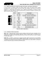
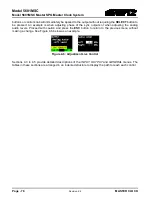
3.4.
CONNECTING TWO 5601MSC UNITS IN SYNCRO MODE
When two 5601MSCs are connected in a redundant configuration with a 5601ACO2 automatic
changeover, it is necessary that both 5601MSC units have the same timing and output settings.
Identical timing for the 5601MSCs is assured by locking both to the same frequency and phase source
(e.g. GPS or by genlocking one unit to the other). Ensuring that both 5601MSCs have the same output
configuration and time can be accomplished by implementing
syncro
between the two units.
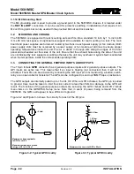
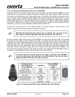
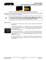
The syncro link is automatically made when the GPIO connector of both 5601MSC units is connected to
the 5601ACO2 using male-to-male DB15 cables. Once the two units are connected, one must be
designated the master unit and the other the slave. The slave unit will copy all the output menu settings
from the master unit so that any change done on the master (such as changing a test pattern or phase
offset) will also be applied to the slave. Additionally, the master 5601MSC can be used as a time
reference by the slave unit, with the time and date being transmitted through the syncro link.
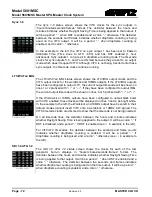
To use syncro, the master 5601MSC must be set to one of the master syncro modes. Likewise, the
slave 5601MSC must be set to a slave mode. See section 4.5.5 for information on these settings. When
the master 5601MSC has been configured to send syncro information and the slave 5601MSC has
been configured to receive it, the state of the link can be viewed on the slave unit by pressing the
STATUS button and selecting the
Inputs
status screen. The slave unit will indicate
Syncro link ok
.
When the link has been established, the slave unit can also set its time reference source to Syncro and
will obtain time through the link as well as menu settings. See section 4.3.4 for details.
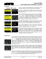
When syncro menu mode is active, all of the menu settings in the OUTPUT root menu are copied from
the master 5601MSC to the slave unit. The menu settings in the INPUT and GENERAL menus are not
affected by syncro. In the OUTPUT menu the SDI TGs and ATGs can be excluded from syncro. This
can be done individually for each test generator (see sections 4.4.3.9 and 0).
3.5.
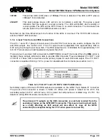
GPS RECEIVER INSTALLATION (GP OPTION)
The 5601MSC unit (with the
GP
option fitted) is designed to work with the Trimble Accutime Gold
antenna. The Smart Antenna houses the GPS receiver, antenna, power supply and other support
circuitry in a sealed, shielded, self-contained unit with a digital interface to the main unit. The GPS
Smart Antenna also receives power from the main unit through the connection cable.
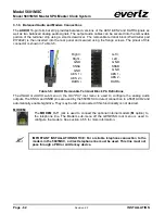
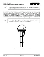
3.5.1. Mounting the GPS Smart Antenna
The smart antenna's enclosure is completely waterproof and is designed for outdoor installation. It is
protected against interfering signals and thus is suitable for reliable operation in most environments.
Select an outdoor location for the antenna, like the roof of your building that has a relatively
unobstructed view of the sky. Dense wood and concrete or metal structures will shield the antenna from
satellite signals. The antenna can receive satellite signals through glass, canvas and thin fibreglass;
thus it may be mounted inside a skylight, if an outdoor location is not possible.
The smart antenna is an active-head antenna. For optimal performance, locate the smart antenna as
far as possible from transmitting antennas, including radar, satellite communication equipment and
cellular transmitters. When locating the antenna near a radar installation, ensure that the antenna is
positioned outside of the radar's cone of transmission. Follow the same guidelines when installing the
antenna near satellite communication equipment. For best results, mount the antenna at least ten feet
away from satellite communication equipment. Do not mount the antenna near high vibration areas
such as fan or motor housings, or near sources of heat such as exhaust stacks.